
© Wonders of World Engineering 2014-


Part 43
Part 43 of Wonders of World Engineering was published on Tuesday 21st December 1937, price 7d.
Part 43 includes a photogravure supplement showing the construction of the great Colorado aqueduct. This section illustrates the article on the World’s Greatest Aqueduct.
The Cover
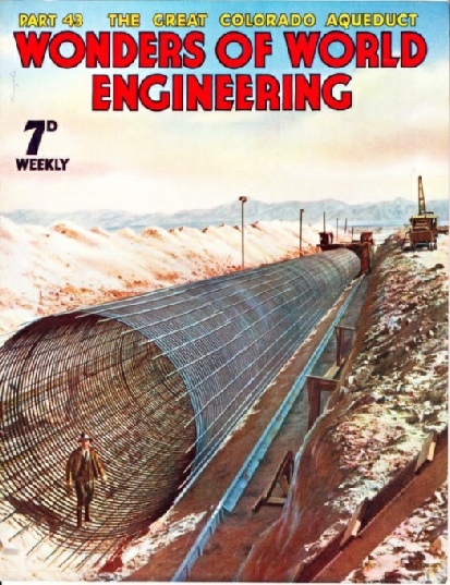
The cover of this week’s Part illustrates a stage in the construction of the world’s greatest aqueduct, which is described in a chapter this week. It is part of an immense scheme carried out by the Metropolitan Water District of Southern California to bring water from the Colorado River, more than 200 miles away, to a group of cities near Los Angeles. The cover shows a section of reinforcement being prepared for one of the inverted siphons, of which there are a considerable number in the course of the pipe line. The inverted siphons were designed to carry the water, by the force of gravity, across the desert country through which the aqueduct runs.
Contents of Part 43
Through Cliff and Warren (Part 2)
How Bicycles Are Built
Water Softeners
World’s Greatest Aqueduct
World’s Greatest Aqueduct (photogravure supplement)
James Watt, 1736-1819
Mixed Traffic Locomotive
Hydroplane Speed Records (Part 1)
Through Cliff and Warren (Part 2)
The story of the building of the line between Folkestone and Dover, in Kent. It was a remarkable feat of railway engineering during the nineteenth century. The route lies along the famous chalk cliffs and through the area of crumbled cliff known as the Warren. The article is the seventh in the series on Railway Engineers at Work and is concluded from part 42.
How Bicycles Are Built
The frame of the safety bicycle, used by the million, is made of seamless steel tubing of the finest grade. Hundred of components are used in the making of every machine. Many of these items are supplied by specialist firms. This chapter describes the highly scientific processes which go to the making of a modern bicycle. The most important feature of the modern bicycle is the fine-grade steel tubing of which the frame is made. There are two main methods of manufacturing this tubing, and both processes will be described in next week’s chapter. The making of the wheels, also, is a particularly interesting process. This is the thirteenth article in the series on the Romance of Industry.
Completed Bicycles
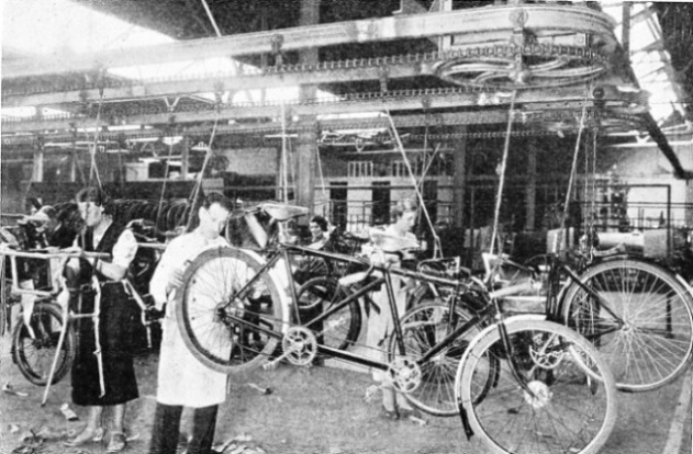
COMPLETED MACHINES undergoing a final inspection before they are packed for dispatch. The bicycles are assembled along the route of an overhead conveyor. The tandem in the foreground is fitted with a special type of changes-peed gear.
World’s Greatest Aqueduct
Photogravure Supplement - 2
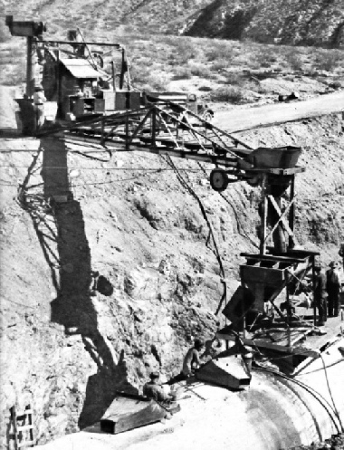
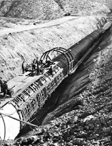
AN INVERTED SIPHON, of which there are 146 in the length of the Colorado aqueduct. Despite their name, they do not exert any siphonic action. In shape they resemble the letter U. They are designed to carry the water across declivities and depressions, the water flowing down one are and up the other to just below the level of the beginning of the siphon. They are built of reinforced concrete, and in the photograph concrete is being poured round the reinforcement. The siphons range in length from 175 feet to 28,400 feet, and cover a total distance of twenty-eight miles.
James Watt, 1736-1819
The patient experiments and inspired research work of James Watt have won him a unique position among engineers. His inventions were responsible for the discovery of a new world of engineering, and his fortunate partnership with the enterprising Matthew Boulton brought him success in his own lifetime. The short biographies which have appeared in this work under the heading “Makers of Engineering History” have proved an exceedingly popular feature. They provide in a handy and readily accessible form a concise record of the lives and achievements of some of the great British engineers. There are two of these men, however, whose work and genius stand out before all others. These men are James Watt and the Hon. Sir Charles Parsons. Their inventions had such complete and far-reaching effects on the whole of engineering practice that it would be impossible to do either of them justice in a single page of Wonders of World Engineering. Watt and Parsons, therefore, will be dealt with in chapters of ordinary length instead of in single pages. James Watt, born in 1736, lived before the days of technical papers, and therefore his achievements are not fully recorded. This drawback has given rise to many stories which cannot now be considered as anything more than inventions. The story of young Watt deriving inspiration for the steam engine from watching the steam blowing the lid off his mother’s kettle, is not in accordance with the known facts, for various forms of steam engine had been in existence long before Watt started his work. Watt started his career as a maker of mathematical instruments. In that capacity he became associated with the University of Glasgow, which used, for demonstration purposes, a working model of the Newcomen engine. This engine is described on page 587 of Wonders of World Engineering. Watt was asked to carry out some repairs on this model and he became so much interested in its operation that he set out to make improvements on it.
World’s Greatest Aqueduct
Photogravure Supplement - 3
ENORMOUS PUMPS lift 1,000 million gallons of water daily to a height of 1,617 feet in the first 100 miles of the Colorado aqueduct. The first set of pumps raises the water 291 feet from the reservoir created by Parker Dam to Gene Wash Reservoir. There are five pumping stations in all. After the first 100 miles the water flows through the aqueduct by gravity.
Water Softeners
Scale formed by hard water on the insides of boilers and of water tubes causes enormous loss of efficiency, sometimes culminating in disaster. Various kinds of water softening apparatus have been devised to overcome this problem and to improve industrial and domestic water supplies. Steam engineers for years have been attempting to overcome the effects of scale on the insides of boilers and of pipes. Scale is a deposit which is formed by the use of what is called hard water, water containing a high proportion of certain chemicals. We can all immediately distinguish between hard water, in which it is difficult to get soap to lather, and soft water, in which soap will lather easily. Hard water, however, is not only a trial for domestic consumers; it is also a serious problem for steam engineers. Several processes have been evolved by which water can be “softened” before it is used, either for industrial or for domestic purposes. These processes are explained in this chapter. There are some huge water-softening installations at work for industrial purposes, and many of the largest in Great Britain are situated in west Cheshire. One in Birkenhead has a capacity of three million and one at Port Sunlight a capacity of two million gallons daily.
Railway Water Troughs at Castlethorpe
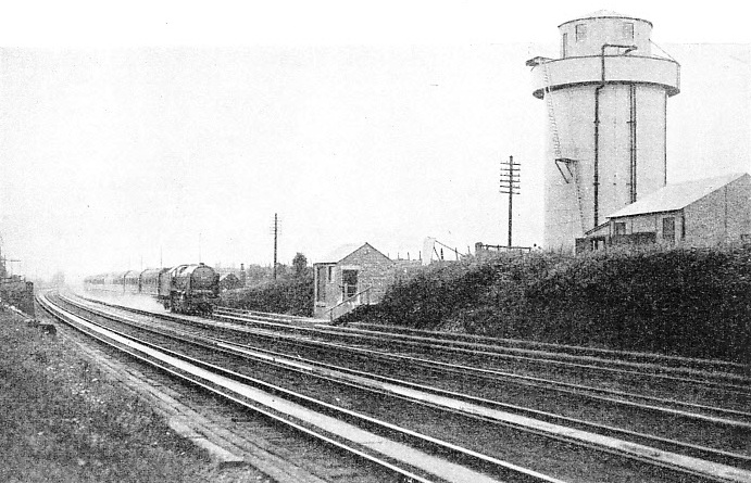
RAILWAY WATER TROUGHS at Castlethorpe, Buckinghamshire, on the LMS (Western Division) main line, are supplied with treated water from the softening plant alongside the line. The plant is of the Lassen-Hjort lime-soda type and has a capacity of 600,000 gallons of untreated hard water a day. A Royal Scot locomotive, at the head of an express train, is picking up water from the troughs at speed.
World’s Greatest Aqueduct
Photogravure Supplement
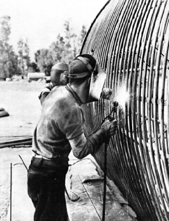
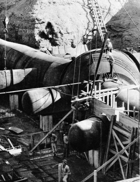
WELDING A REINFORCEMENT FRAME for a section of the Colorado aqueduct. Electric arc welding is generally used for such work. As the electric arc is the hottest flame known, the head of the welder must be protected with a helmet, the hands with gauntlets and the body with a leather or woven asbestos apron. From the electrode holder, held in the operator’s hand, there trails the negative pole cable from the source of electricity. Electric arc welding is described in the chapter which begins on page 437 of this work.
James Watts’ Workshop at Heathfield
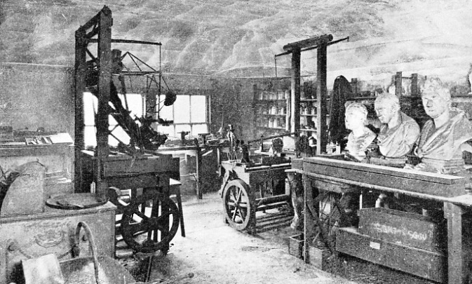
INTERIOR OF THE WORKSHOP in which James Watt, in his later years, worked at Heathfield, near Birmingham. With the expansion of that city, the site was required for other purposes, and the contents of the workshop were removed and installed, exactly as left by him, in a replica of the room at the Science Museum, South Kensington.
Mixed Traffic Locomotive
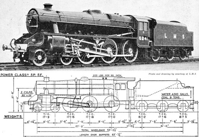
ONE of a numerous and successful class of LMS 4-6-0 mixed traffic locomotives , No. 5241, is illustrated below. The first of the class, No. 5020, appeared in 1934 and since then no fewer than 452 have been built or ordered. These engines were designed for general utility work on all sections of the LMS, and they can haul lightweight expresses and heavy freight trains with equal competence. The later examples of the class, including No. 5241, differ in detail from the earlier engines.
Each engine has two cylinders, 18½ in by 28 in, placed outside the frames and driving the second coupled axle. Walschaerts valve gear and piston valves are fitted. The valve travel is 6½ in. The driving wheels are of 6 feet and the bogie wheels of 3 ft 3½ in diameter.
The boiler barrel has a length of 13 ft 10⅛ in and tapers from 4 ft 11 11/16 in to 5 ft 8½ in outside diameter. Top feed is provided and the later members of the class have domes. What appeared to be a squat dome in the earlier engines was the top feed cover. The Belpaire firebox is fitted with “pop” safety valves, the working pressure being 225 lb per square inch.
The tubes have 1,460, the firebox 171·3 and the superheater 307 square feet of heating surface, the total, including superheater, being 1938·3 square feet. The firegrate area is 28·65 square feet. Tractive effort, at 85 per cent boiler pressure, is 25,455 lb. The engine weighs, in working order, 70 tons 12 cwt, of which 53 tons 3 cwt are available for adhesion.
The six-wheeled tender accommodates 4,000 gallons of water and 9 tons of coal. The weight is 54 tons 13 cwt. Total weight of engine and tender, in working order, is 125 tons 5 cwt. Despite the relative smallness of their driving wheels, these locomotives have been timed at speeds in excess of ninety miles an hour on favourable gradients. Nos. 5278 and 5264 did exceptionally well on test runs made in April 1937 over the Midland Division of the LMS, between London (St. Pancras) and Manchester (Central).
This route abounds in heavy gradients. Between Derby and Manchester, a distance of 61·4 miles, it runs through the Peak District of Derbyshire and climbs to a height of nearly 1,000 feet above sea level, with long stretches as steep as 1 in 90. Yet No. 5278 hauled a load of 258 tons over this route at an average speed of 54·1 miles an hour from start to stop. In the southern section of the route, the 99·1 miles from Leicester to St. Pancras were covered by No. 5264, also hauling 258 tons, in 92½ minutes, at an average speed of 64·1 miles an hour.
This is the twenty-second article in the series Modern Engineering Practice.
Sir Malcolm Campbell at the Wheel of Blue Bird
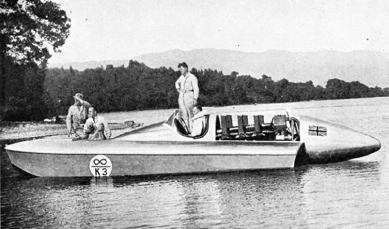
SIR MALCOLM CAMPBELL AT THE WHEEL of his hydroplane, Blue Bird, during preliminary trials on Loch Lomond, Scotland. Blue Bird was only 23 feet long on the waterline, and had a beam of 9 ft 6 in. Although various light metals were used in her construction, she was built mainly of wood, and in full trim weighed only 45 cwt.
The Great Landslip of 1915
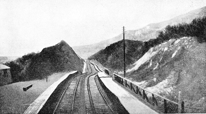
AFTER THE GREAT LANDSLIP OF 1915. On December 19 of that year occurred one of the greatest landslides known in the Warren district. Warren Halt, shown above, and the neighbouring section of line were carried bodily a distance of 159 feet towards the sea.
World’s Greatest Aqueduct
Water for thirteen cities in southern California is brought from the Colorado River, across deserts and beneath mountains, in an aqueduct 242 miles long. Other aqueducts, built for distribution purposes, bring the total length of pipe to nearly 400 miles. One of the most remarkable examples of engineering works undertaken to provide a water supply for a large population is described in this chapter. Water for the cities in the neighbourhood of Los Angeles, California, is brought a distance of nearly 300 miles from the Colorado River in an immense aqueduct. The building of this great aqueduct is but one of the major engineering feats undertaken for the supply of water for this region.
A Wooden Jumbo
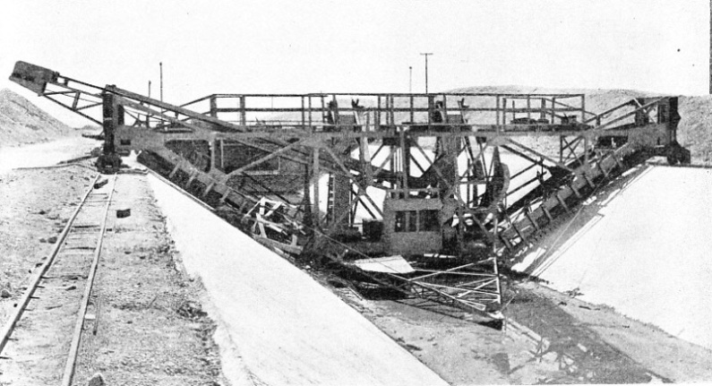
A WOODEN JUMBO, or moveable scaffold, straddled the canal section of the Colorado aqueduct and ran on rails on either bank. From the jumbo workmen finished the concrete lining, which had been laid by a special machine. Sixty-two miles of the aqueduct were formed by open lined canals, dug to a depth of 11 ft 7 in and 60 feet wide at the top.
Hydroplane Speed Records (Part 1)
The development of the racing hydroplane has been so rapid that speeds have been increased from 60 miles an hour to 130 miles an hour during the last twenty years. In September 1937 Sir Malcolm Campbell regained the record for Great Britain with his Rolls-Royce engined Blue Bird. He attained a speed of 129½ miles an hour on Lake Maggiore. Such a speed is a remarkable tribute to the achievements of engine designers and builders. This chapter tells the story of the world’s water speed record. The article is concluded in part 44.
