


© Wonders of World Engineering 2014-


Water for thirteen cities in southern California is brought from the Colorado River, across deserts and beneath mountains, in an aqueduct 242 miles long. Other aqueducts, built for distribution purposes, bring the total length of pipe line to nearly 400 miles
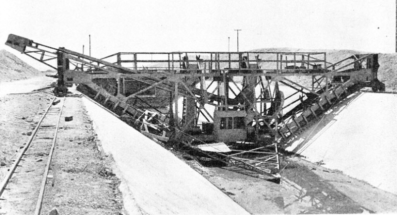
A WOODEN JUMBO, or movable scaffold, straddled the canal section of the Colorado aqueduct and ran on rails on either bank. From the jumbo workmen finished the concrete lining, which had been laid by a special machine. Sixty-
TO provide the great centres of population with an efficient water supply the engineer has often to tap lakes and springs many miles distant and to bring the water to the cities through aqueducts. Manchester obtains some of its water from Thirlmere, one of the lakes in Cumberland, through a pipe line ninety-
The greatest of these aqueducts is the 242-
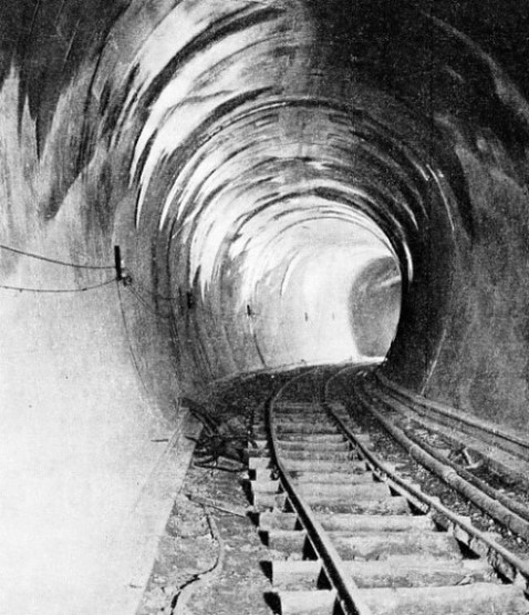
The main aqueduct was not built across ordinary terrain, but in desert and in wild, mountainous country. The mountains were pierced by tunnels. In boring these tunnels the men had narrow escapes from drowning. Unforeseen difficulties constantly arose, and over and over again the engineers were called upon to fight, against almost overwhelming odds. The laying out of the canals and conduits and the erection of the great siphons proved no easy task. New and elaborate machinery was devised to meet special conditions. The interior of the great tube, which has a diameter of 16 feet, large enough to accommodate a modern locomotive, has been finished to the smoothness of steel throughout its entire length of 242 miles, with no sharp curves or rough places, so that the flow shall not be retarded.
This giant tunnel was built for the Metropolitan Water District of Southern California, a body responsible for supplying water to a group of thirteen cities in that section of the State. Southern California is semi-
The water in these underground reservoirs, however, which was formerly the chief source of supply, represents the accumulation of many thousands of years. The rapid growth of the cities, from a population of 60,000 in 1870 to about 3,000,000 in 1936, increased the consumption of water from, the underground reservoirs to 200,000,000 gallons daily — more than Nature replaces. These water basins, then, were being rapidly drained away, and it was essential to seek water elsewhere.
After careful engineering and economic study and investigation, extending over a period of nine years, during which more than 25,000 square miles of rugged mountain and desert country were surveyed, it was decided to bring water from the Colorado River. It was the nearest point from which the large volume needed — 1,000,000,000 gallons a day — could be obtained. More than a hundred different routes were proposed, and the one finally selected was that known as the Parker Route. Parker is the name of a settlement in Arizona, close to the Colorado, 155 miles below the Boulder Dam.
From this point to Riverside (ten miles from Cajalco Reservoir, from which the water will be distributed to the various cities) the country is barren and mountainous. In this wild and desert region the surveying party spent several seasons mapping the course of the aqueduct. All supplies, including provisions, water and tools, had to be carried with them. In the desert the thermometer often registered 130° Fahrenheit in the shade, and on the mountain tops the party had to force a path through deep snowdrifts at a temperature far below zero.
When the route had been decided upon, there came the building of hundreds of miles of highways, over which men and heavy machinery and material could be conveyed. There were thirty of these camps scattered along the route, model establishments of their kind, with dormitories where the men were comfortably lodged and fed and their general health was looked after. At conveniently reached centres there were also well-
Work was begun in 1932 under the direction of Frank E. Weymouth, who was for many years Chief Engineer of the United States Reclamation Service and an authority on water supply. Soon an army of men, totalling about 8,000, was spread along the route to engage in various tasks under the guidance of competent engineers. Some of the work was let out by contract, though the greater part was carried out by the Metropolitan Water District. By June 1937 the main aqueduct was finished, with the exception of a short length of tunnelling and the installation of some of the great pumps for lifting the water over the mountains.
 At Parker, on the Colorado River, 155 miles below the Boulder Dam, a diversion dam was built to create an intake and a great storage basin 700,009 acre feet in extent. Parker Dam, a massive concrete structure of the arched type, was built by engineers of the United States Bureau of Reclamation while the Boulder Reservoir was being filled. The building of the dam enabled the work to be carried out while the water in the river was low.
At the same time it was found necessary to build a tunnel through the cliffs to divert the flow while the foundation of the dam was being secured.
THE TUNNEL LINING of the underground sections of the aqueduct was finished as smooth as glass to offer the least resistance to the flow of water. There are ninety-
The problem that faced the engineers was the great depth of the silt—243 feet. It was necessary to drive steel sheet piling down through the entire depth of this silt to reach bedrock and so to procure a solid foundation and prevent seepage. From foundation to summit the retaining wall measures 335 feet. The height of the water in the basin is controlled by five roller bearing gates built of ½-
The dam has raised the water about 72 feet above its old level. At this depth there is sufficient water for the aqueduct and also to supply the 80,000 horsepower hydro-
During the first 100 miles there are five of these pumping stations and the aggregate height to which they will lift the water is 1,617 feet. From the intake the water is pumped to Gene Wash, a lift of 291 feet. Here it is again lifted 303 feet to Iron Mountain, whence it is lifted another 144 feet to Eagle Mountain; it is again lifted 438 feet to Hayfield, whence it is finally raised another 441 feet. From this point the water flows by gravity.
The pumps are installed at each plant in batteries of three. The engineers were aware that the best available equipment
showed an efficiency of some 80 per cent. They also knew that for each one per cent increase in pumping efficiency £10,000 a year would be saved. The engineers at the California Institute of Technology were requested to study the problem, and experimental tests were carried out. Pumps were built in miniature and water was lifted to scale.
As a result of experiments generators, fed by power from Boulder Dam, turn the centrifugal pumps whose runners (vanes) pick up the water and force it uphill with an estimated efficiency of 90 per cent. This 10 per cent increase in efficiency is claimed to represent a saving of £100,000 annually in pumping costs alone.
The water flows from the intake at Parker through the great pipe line across desert and through tunnels in the mountains for a distance of 242 miles into Cajalco Reservoir, the end of the main aqueduct. This pipe line is made up of ninety-
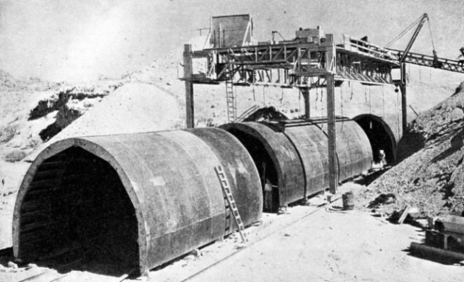
COLLAPSIBLE STEEL FORMS were used in building the fifty-
Unforeseen difficulties were experienced in boring the tunnels. There are twenty-
The machinery used in excavating the tunnels was of the latest type. Great drill carriages, mounting as many as four to eight pneumatic drills, were used. With these machines from twenty to sixty holes, from 5 feet to 12 feet deep, were driven into the rock. Explosives were then rammed into these holes and fired. After the blast, the shattered rock, or muck, was loaded on to waiting cars and hauled out to the dump. On tunnels where vertical shafts were used the cars were hoisted, one by one, to the surface on cages.
Several types of “mucking machines” were used. The one most generally used shovelled up the muck in an electrically operated dipper and tossed the broken rock on to an endless belt, which conveyed it to a dump car attached to the rear end of the machine.
“Cherry-
Other types had swinging booms, designed to operate in the cramped space of a tunnel, which dropped the muck directly into the cars. In many of the tunnels the cars were shifted by a pneumatic hoisting arrangement called a “cherry-
The great automatic drills, the safety blasting caps with their delay fuses, the rapid loading and removal of the muck cars and the huge ventilator pipes, designed to supply pure air to the workers at the tunnel facing and to suck out the poisonous and acrid fumes after blasting, enabled the tunnelling to proceed at a pace never before known. Until a few years ago, a crew of miners could shoot only one round, breaking down 4½ feet of rock in an eight-
Although records were set up for speed in tunnel driving, the work was considerably hindered by tapping large volumes of pent-
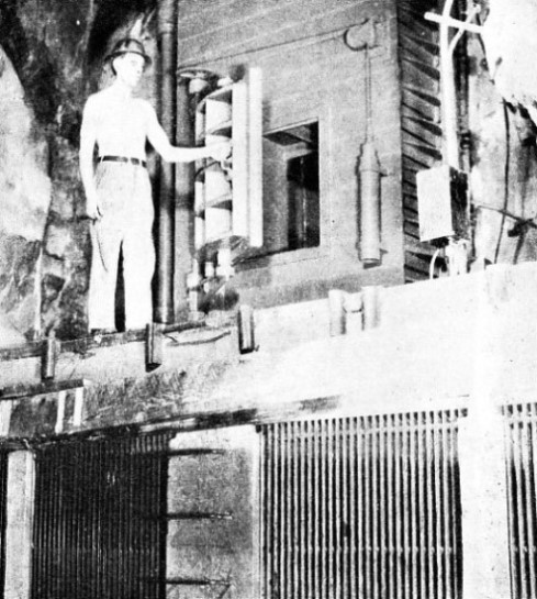
T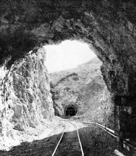 hese pumping stations were guarded by massive steel doors. They were never opened except for the delivery or removal of machinery. Attendants entered the stations through tiny openings in the doors, each scarcely large enough for a man to crawl through. By means of these pumps the engineers were able to lock within the mountain large quantities of water and to remove the vast volume which poured into the tunnels.
TWO TUNNEL PORTALS at an early stage in the construction of the Colorado aqueduct. The tunnels were driven at a fast rate, with the help of great pneumatic drills, efficient spoil-
Before the pumping plants were installed the men had several narrow escapes. On one occasion a blast caused a cave-
When treacherous ground was encountered the drillers moved ahead with a pilot drift — a small tunnel the height of a man. They placed supporting timbers as they went. These drifts were driven 30 feet to 40 feet ahead of the main tunnel. The narrow opening was then gradually widened out fan-
In water-
Largest Siphons Yet Built
Work in the tunnels had to be constantly checked, as the slightest deviation in grade or angle might prove serious. The surveyors’ difficulty here was the question of adequate lighting to enable them to read the finer observations of their delicate instruments. This was solved by the introduction of a powerful lamp allowing only a fine vertical beam of light to escape. Men were able to sight upon this slender beam from great distances down the tunnel. For other types of observation, pocket flashlights were suspended from the roof of the tunnel.
 Tunnel driving, however, was only one phase of the undertaking, which included the canals, conduits and siphons. There are twenty-
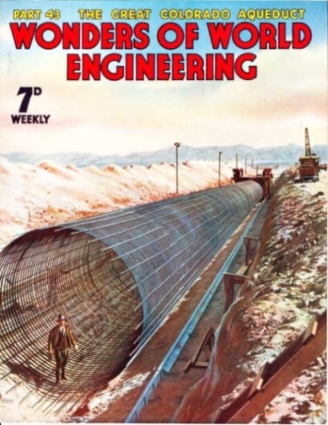
This cover illustration shows a section of reinforcement being prepared for one of the inverted siphons, of which there are a considerable number in the course of the pipe line. The inverted siphons were designed to carry the water, by the force of gravity, across the desert country through which the aqueduct runs.
It was necessary for the siphons, conduits, tunnels and canals to be finished as smooth as glass. There are no sharp curves, projections or rough spots, for these would greatly retard and reduce the flow of water. If the tunnels had been left in the “rough”, to cope with the proposed flow, they would have had to be given a diameter of 18 feet instead of 16 feet. Special machines were designed for building the canals to ensure this streamline effect.
One of the most interesting of these machines was the trimming machine, which straddled the 60-
When the canal had been cut to the desired depth, 11 ft. 7 in., with a width at the top of 60 feet, its sides and bottom were quite smooth. Steel reinforcing rods were then laid down and all was ready to receive the concrete.
Formerly, after the bed of a canal had been smoothed by hand methods, the bottom was paved, and then the concrete was laboriously set on the sides by hand. In the Colorado aqueduct, however, this was accomplished in a single operation by an ingenious mechanical device known as a paver. The paver not only laid the concrete, but also spread it evenly and tamped it down. In design the paver resembled a huge rolling bridge mounted on trucks running on rails parallel to the canal banks. It weighed 48 tons and was formed to the shape of the finished canal.
 Concrete was supplied to the paver from a mixer. This was mounted on crawler treads to allow it to follow the paver as it moved along. The concrete ran down through special hoppers on to the floor of the canal. As it emerged from the machine, revolving steel rods were brought into play. They spread the concrete over the ground evenly and tamped it down firmly, achieving a glass smooth trowel finish.
HEAVY STEEL DOORS guard the entrance to the huge underground pumping stations, far beneath the San Jacinto Mountain. These powerful pumping stations were installed to keep the tunnel workings free from the underground waters which were released by drilling operations. The massive steel doors were opened only for the installation or removal of machinery. Workmen entered and left through the small door.
The concrete for the canal sides was delivered through a number of small apartments, or pockets, when another series of revolving rods was used. They were so. designed that they not only spread the concrete out evenly, but also prevented the plastic material from moving sideways down the slope. As the machine progressed, finishers followed behind, and from framed wooden jumbos, or movable scaffolds, mounted on rails, worked over the surface of the concrete with hand-
When moving at a speed of about 1 foot a minute one of these machines paves approximately 500 feet, placing over 700 cubic yards of concrete in position during one eight-
Within the tunnels, conduits and siphons, workmen ground down inequalities, particularly at joints, with high-
and through the heart of great mountains, is there a sharp corner. Thus friction is reduced to a minimum and water is permitted to flow with little restraint.
The flow of water through an aqueduct of such great length, especially when dependent on constant pumping, is liable to temporary interruptions. Occasions will arrive when the flow has to be temporarily suspended to allow for renovation and repair of machinery and perhaps of damage to the line. Hence the necessity of a terminal storage to ensure a constant supply to the cities. This has been met by the creation of Cajalco Reservoir, some ten miles from the town of Riverside.
Water Travels 400 Miles
The site of this storage basin is a depression among the mountains. It has been formed by the erection of an earthern dike on its northern side, and of an earthern dam on its western side. Some 250,000 wagon-
rollers, filled with water and studded with steel spikes resembling sheep’s feet. As the rollers moved back and forth across the rising surface of the dam the spikes penetrated the surface, kneaded the grains of soil, packing them so closely that the earth dam now absorbs little water.
The capacity of the reservoir is 100,000 acre feet, which can be increased, as desired, up to a capacity of 228,000 acre feet. A huge lake, four miles in length and two miles across at its greatest width, was thus formed among the mountains. From this storage basin the water is distributed to thirteen cities, namely, Anaheim, Beverly Hills, Burbank, Compton, Fullerton, Glendale, Long Beach, Los Angeles, Pasadena, San Marino, Santa Ana, Santa Monica and Torrance. When the water reaches these cities it will have travelled a distance of nearly 400 miles.
The cost of this great water scheme is £44,000,000. The water is sold to the cities at £3 an acre foot (326,700 gallons). Although the primary object of the aqueduct is to supply the cities with water, it is also proposed to bring more than 2,000 square miles under cultivation in a region where oranges and lemons and similar fruit grow in profusion.
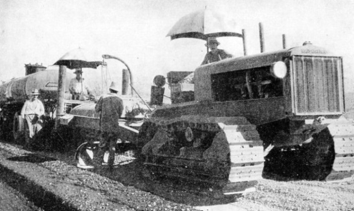
ROAD WORKS IN THE DESERT were carried out with the help of powerful crawler tractors, sometimes in a temperature of 130 degrees Fahrenheit in the shade. Hundreds of miles of roads had to be built across mountain ranges and desert, to convey men and materials for the building of the 242-
Click here to see the photogravure supplement to this article.