
© Wonders of World Engineering 2014-


Part 44
Part 44 of Wonders of World Engineering was published on Tuesday 28th December 1937, price 7d.
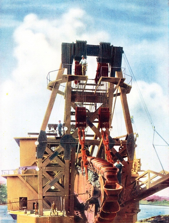
Part 44 includes a colour plate showing one of the largest gold dredges operating in North America. It formed part of the article on Gold-Dredging Machinery .
The Cover
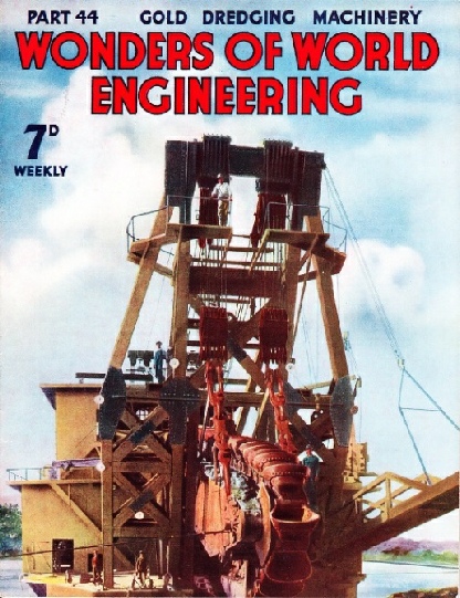
The cover this week is reproduced as a colour plate; the original photograph was supplied by courtesy of Ruston-Bucyrus Ltd . It shows the front end of one of the great gold dredges operating in the Western States of North America. Gold-bearing soil and gravel are brought up on an endless chain of buckets, as described in the chapter which begins on page 1257.
Contents of Part 44
Hydroplane Speed Records (Part 2)
Engines Under Test
The Electric Totalisator
Gold-Dredging Machinery
Gold-Dredging Machinery (colour plate)
Guglielmo Marconi
Monumental Engineering
Bridging the St Lawrence (Part 1)
Engines Under Test
One of the most valuable tests of the efficiency of an engine - whether a reciprocating steam engine, a steam turbine or an internal combustion engine - is the measurement of its horse-power . Horse-power is measured by dynamometers of various kinds. This chapter deals with the testing of steam and oil engines. The power of an engine is measured by some form of brake dynamometer. Dynamometers vary in size and in detail, but the principle is virtually the same in all instances. This chapter explains how the dynamometer gives and accurate indication of the power of an engine.
The Rolls-Royce Kestrel Engine On Test
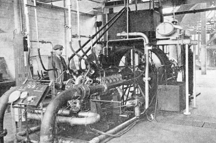
AIRCRAFT ENGINE ON TEST. The Rolls-Royce Kestrel supercharged engine illustrated has twelve cylinders. On the ground it develops about 785 horse-power at 2,500 revolutions a minute. Crank speeds up to 3,000 revolutions a minute are permissible. The testing of internal combustion engines involves many factors not present in steam engines, but all the power developed may similarly be measures by a brake or hydraulic dynamometer.
Hydroplane Speed Records (Part 2)
The story of the world’s water speed record. The article is concluded from part 43.
Guglielmo Marconi
Although the nature of wireless waves was not unknown when Marconi started his experiments; it was he who made practicable the use of their properties. The enormous value and scope of radio transmission to-day has been developed from his brilliant discoveries and untiring research.
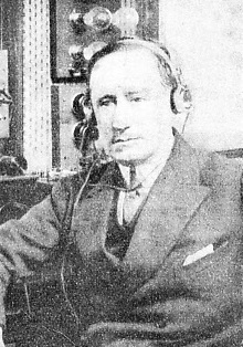 Any passer-
by at Signal Hill, Newfoundland, on December 12, 1901, might have been excused for thinking that the man to be seen there flying a kite was simply attempting to repeat Benjamin Franklin’s famous experiment of some 150 years earlier.
The two experiments had two things in common. Both were made in the hope of obtaining an electrical discharge from the upper regions of the air, and both were successful. Franklin proved by his kite-flying that the awe-inspiring lightning flash was of the same nature as the spark from the Leyden jar. Marconi showed that an infinitely smaller discharge could be sent across the ocean in a curved path and made to report itself 2,000 miles away. To-day a commonplace radio transmission over such a distance was then considered to be impracticable by so many people that Marconi hesitated for two days after the experiment before he sent a cablegram to England announcing his achievement.
Marconi's place in the history of engineering is secured by the fact that his genius enabled him to foresee the possibilities of, and to bring to pass, the harnessing of the waves so that they could be used to convey messages over distances of thousands of miles instead of merely announcing their presence to an apparatus a few hundred feet away.
This is the fifteenth article in the series Makers of Engineering History.
The Chain of Buckets in a Gold Dredge
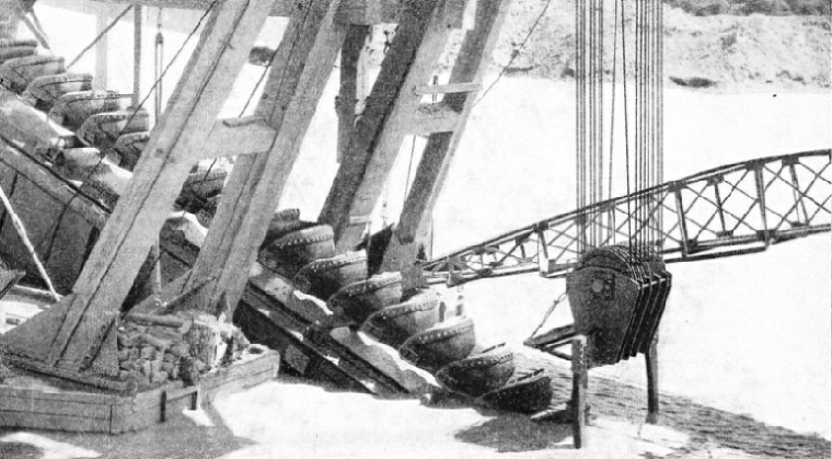
THE ENDLESS CHAIN OF BUCKETS in a Californian gold dredge will bring in as much as 500 cubic yards an hour of gold-bearing gravel from depths as great as 100 feet. Each of the buckets of the dredge illustrated weighs 1,750 lb and has a capacity of six cubic feet.
Control Switchboard for a Totalisator
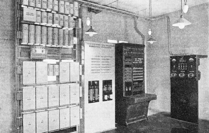
CONTROL SWITCHBOARD for a totalisator installation at a greyhound racecourse. The small switchboard near the centre of the illustration controls the operation of the entire apparatus. Keys on this board control signal lamps at the ticket issuing booths; other keys lock the apparatus electrically; and switches, controlled by a lock, start and stop the operation of the whole totalisator.
Blue Bird on Lake Maggiore
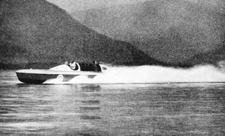
A FAST RUN ON LAKE MAGGIORE, on the smooth surface of which Blue Bird eventually attained a speed of 130·43 miles an hour. The above illustration shows the boat with her streamlined tail in position; this tail was removed during the record run, as it was necessary to modify the water-cooling system and to discharge the water at the stern of the boat.
One of the Largest Gold Dredges Operating
ENDLESS CHAIN OF BUCKETS on one of the largest gold dredges operating in the Western States of North America. Each bucket has a capacity of 15 cubic feet, and weighs about two tons. The buckets are strongly built, being fitted with lips of special steel. There may be as many as a hundred buckets on the chain. Sometimes masses of rock come on board in the buckets and the machinery has to be stopped while the rock is rolled overboard again.
This colour plate is also reproduced on the cover of this part.
Gold-Dredging Machinery
The gold-bearing valleys in the Western States of North America are dredged by machines each of which may cost as much as £100,000 to build. The dredges recover enormous quantities of gold, and they are able to work in waterlogged soil where mining operations are impossible. A colour plate accompanies this article, showing one of the immense gold dredges which are used in the gold-bearing valleys of California. The great machines, and their methods of operation, are described in this chapter.
Monumental Engineering
In various parts of the world there are outstanding examples of the skill of craftsmen thousands of years ago. The pyramids and obelisks of Egypt, the stone circles at Stonehenge and the mysterious statues of Easter Island are among the timeless monuments of bygone ages. Over the north door of St. Paul’s Cathedral, London, is the famous epitaph of Sir Christopher Wren: Si monumentum requiris, circumspice - “If you seek his monument, look about you”. These words would be a fitting epitaph for all the great engineers who have built structures, such as the Forth Bridge and the Panama Canal, for instance, which will long outlast their designers. All the great engineering structures of the world are lasting monuments to the engineers who built them, and in the world to-day there are many monuments to the unknown engineers of past ages. Take, for instance, the Great Pyramid, in Egypt. It is so old that even its date cannot be determined exactly, yet it must have been planned and built with extra-ordinary science and skill for it to have lasted for so many thousands of years. The famous stone circle known as Stonehenge, on Salisbury Plain, in Wiltshire is another remarkable example of works lasting for so long that the methods of their construction have become a matter of controversy. These and other famous examples of what may be described as monumental engineering are the subject of this chapter. This chapter covers a large field, for he discusses matters ranging from the monuments of ancient Egypt and the extraordinary statues on Easter Island, in the Pacific Ocean, to more recent examples of monumental engineering in Russia, France, Great Britain and the United States.
Stonehenge
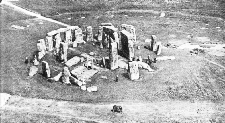
THE STONE CIRCLES of Stonehenge, on Salisbury Plain, Wiltshire, were erected thousands of years ago. The outer ring of stones has a diameter of 108 feet and consisted of thirty huge monoliths with lintels mortised to them. Sixteen uprights and five lintels remain. The white patches in the background mark the site of the stones of a now vanished outer circle. The inner circle of monoliths originated in South Wales; these stones were probably brought to Wiltshire by water as far as Amesbury.
Bridging the St Lawrence (Part 1)
The story of the Quebec Bridge is a story of triumph after disaster. On two occasions thousands of tons of steel collapsed and fell into deep water. Undaunted, those in charge persevered and completed an invaluable link in transcontinental communications. North America was the scene of one of the finest epics in the history of bridge building. Quebec Bridge, which spans the St. Lawrence River, took seventeen years to build. On two occasions disaster overwhelmed the structure, but in face of tremendous difficulties the engineers finally completed the bridge. In 1907, when work had been in progress for seven years, 17,000 tons of steel collapsed, some falling into the river, which is here 200 feet deep, and the rest crashing on the pier and on the bank in a fearful tangle of twisted plates and girders. Years passed before the damage could be repaired and the work finished. By 1916 the cantilever arms and anchor arms on either bank were completed and the bridge was ready for the erection of the centre 640-feet span. This was floated into position and raised to the level of the cantilever arms by hydraulic jacks and lifting appliances. The job was nearly finished when without warning the great span, containing 5,000 tons of steel, broke away and fell into the deep water. A new span had to be built, and in September 1917 the bridge was at last finished.
This chapter is the fifteenth in the series on Linking the World’s Highways and the article is concluded in part 45.
The Electric Totalisator
The skill of the electrical engineer and the experience amassed by the telephone engineer have made possible the design of a complex instrument to which vast sums of money are entrusted every day. Although electric totalisator machines are seen only at racing tracks, they are amazingly complex structures of the greatest interest to engineers.
