One of the most valuable tests of the efficiency of an engine—whether a reciprocating steam engine, a steam turbine or an internal combustion engine—is the measurement of its horse-power. Horse-power is measured by dynamometers of various kinds
AIRCRAFT ENGINE ON TEST. The Rolls-Royce Kestrel supercharged engine illustrated has twelve cylinders. On the ground it develops about 785 horse-power at 2,500 revolutions a minute. Crank speeds up to 3,000 revolutions a minute are permissible. The testing of internal combustion engines involves many factors not present in steam engines, but the power developed may similarly be measured by a brake or hydraulic dynamometer.
RUNNING tests of various types of motive power units are carried out at the maker’s works, for two main reasons.
First, they enable the manufacturer to assure himself that the engine is in perfect working order and will carry out the terms of the buyer’s requirements before it passes out of his own hands. In this way he can make any slight adjustments or modifications which may be found necessary and which are more easily and cheaply done on the spot. Secondly, these tests enable the buyer to satisfy himself that the engine complies with the specified conditions before it is accepted. In many instances the buyer, has no suitable means for carrying out local tests, and all the leading makers of steam reciprocating engines, steam turbines and oil engines have at their own works elaborate provision for doing so. Such tests are also valuable for purposes of research. Even after a century of experience the reciprocating steam engine is still open to improvement. Steam turbines are subjected to most elaborate tests to find out the most efficient pressures and temperatures at which they will run, the most economical methods of feedwater heating and so on.
The internal combustion engine, whether using gas, petrol or the heavier oils, affords great scope for research in testing the numerous factors affecting its efficiency and general performance. These include such questions as the best compression ratios, ignition pressures, supercharging and temperatures under varying loads. Some of these questions involve laboratory work, to be carried out by specialized technicians, but the methods generally adopted for commercial testing are of great interest and importance. The testing department of an engine-builder’s works is generally placed at one end of, or close to the erecting shop, so that when the engine has reached the final stage of erection it can, if not large, be lifted bodily by an overhead crane on to its testing bed. Still larger engines may have to be erected on the bed on which they will be tested.
With steam engines the boilers necessary for supplying the steam may be specially reserved for the purpose, or those supplying power to the works may be commandeered to supplement the steam supply from a test boiler.
As the most satisfactory way of measuring the steam used by an engine is to condense it and weigh the condensed steam, condensing plants are often installed. Even for engines which are not intended to run with a vacuum the steam may be condensed in the same way, but at atmospheric pressure, to be in approximately the same condition. This also involves the use of pumps, measuring tanks and other accessories in connexion with the boilers and the condensing plant.
Neither of these plants is, however, necessary when testing internal combustion engines, but there are a few firms which make both steam and oil engines. The testing plant then has to be suitable for each type of engine.
For steam reciprocating engines the chief points on which test results have to be obtained relate to the measurement of the power the engine will develop in certain conditions; the quantity of steam that it requires for each horsepower unit developed; the action of the governor in fluctuating load conditions; and other functions bearing on its general performance.
Several appliances and instruments are required for measuring the power and enabling observations to be made of those points on which definite information is wanted. When the engine is tested alone, without anything such as an electric generator coupled to it, the power is measured by some form of brake dynamometer, the type used depending on the size of engine. For smaller engines a simple form of friction brake is sometimes adopted. This may take the form of a brake wheel, or drum, mounted on or coupled to the engine crankshaft. Two or more ropes, joined together at the two ends, are placed round the upper half or round the whole circumference of the wheel, and are prevented by wooden guide blocks from slipping off while running. One end of the ropes is attached to an anchored spring balance; to the other end is hung a set of detachable weights, so that the weights are pulling against the directional pull of the engine.
The measurement of power is the measurement of the rate of doing work in a given unit of time, and the foot-lb. — or the force of one pound acting through a distance of one foot in one minute — is the unit standardized for this purpose. One horse-power is the equivalent of 33,000 foot-lb. of work-done in one minute.
Formula for Brake Horse-Power
In a friction brake dynamometer the force is represented by the weight (W) applied at the wheel radius. The distance travelled is obtained by multiplying the circumference of the brake wheel (2 r) by the number of revolutions a minute (N). Thus, neglecting certain refinements, the investigator, knowing the suspended weight (W) in pounds and the diameter of the wheel in feet, as well as the speed in revolutions a minute, is able by simple arithmetic to arrive at the foot-lb. a minute. Dividing that result by 33,000 will give the “brake” horse-power which the engine is developing at a given time. Thus the formula is W x 2 r x N divided by 33,000.
With larger engines, steel brake straps with wooden blocks bearing on the wheel rim are sometimes used instead of ropes. The friction caused in these conditions generates considerable heat, which has to be dissipated. One way of doing this is to provide side flanges on the inside of the wheel rim, to form a trough. While the engine is running, a constant stream of cold water is fed into the trough, and is continuously drawn off the trough by another pipe with a scoop at the end of it. The brake wheel must be kept sufficiently, but not excessively, lubricated.
Various modifications of this type of brake are used, and in most of them some means of quickly applying or releasing the strap is provided. This is useful when taking governing tests of sudden variations in the load, or for safety reasons. In the larger sizes of brake the use of dead weights would be cumbersome; so the pressure is applied at the end of a long lever pressing on a weighing machine, or carrying less weight.
When the power developed is so great as to involve the generation of more heat than can be easily dissipated in this way, the Froude type of hydraulic dynamometer is extensively used. This was invented by the late Dr. William Froude, and is used for all kinds of testing purposes. The hydraulic dynamometer is now often used, even for moderate-sized engines.
ABSORPTION DYNAMOMETER connected to a high-speed diesel engine of 100 horse-power. Special steel disks, fitted with vanes, are fixed to the shaft of the dynamometer inside the casing. Water is admitted and the resistance set up is transmitted to the casing, which would rotate if it were free to do so. This is prevented, however, by the attachment of calibrated weights and a spring balance, and the pull recorded on the spring balance is proportional to the power absorbed.
In its main principle this appliance is approximately equivalent to the reverse of a water turbine. Instead of the water pressure driving the rotating turbine wheel, as it does in the water turbine, the rotor wheel of the dynamometer is driven by the engine being tested, and drives out the water which is fed into it. The machine consists essentially of a rotor carried on a shaft and running inside a casing. The shaft is supported by bearings fixed in the casing, and not in external supports. The casing is carried by anti-friction trunnions containing ball or roller bearings, so that it is free to swivel about the same axis as the main shaft.
When on test the engine is directly coupled to the main shaft which transmits the power to the rotor revolving inside the casing, through which water is circulated to provide the hydraulic resistance and simultaneously to carry away the heat developed by the absorption or destruction of power. In each face of the rotor are formed pockets, or cups, of semi-elliptical cross-section divided from one another by oblique vanes. The internal faces of the casing are also arranged with a corresponding number of pockets.
When in action, water is supplied to the pockets through holes in the vanes. The water is then discharged by the rotation of the rotor into the pockets formed in the casing, and a vortex action is set up, water being constantly circulated round each elliptical space formed by the rotor and casing pockets. The resistance offered by the water to the rotation of the rotor reacts upon the casing, which tends to turn on its anti-friction supports. This tendency is counteracted by a lever arm ending in a weighing device comprising either a spring balance or a steelyard, in combination with loose balance weights.
These dynamometers have lever arms of such length that the power absorbed can be easily calculated by a simple formula. The load on the dynamometer can be altered at will while running by infinitely small gradations between maximum and minimum, without changing any part of the dynamometer.
The steam consumption of an engine is measured in pounds an hour, and also in relation to the horse-power developed at the same time, so that the weight of steam used and the horsepower will have to be measured.
Measuring Steam Flow
The steam may be measured by one or more methods. If the engine is alone served by a boiler, the amount of steam generated by the boiler during the test period can be obtained; but this introduces several factors which have to be allowed for. A simple method of measuring steam flow is by means of a steam flow meter, which is generally calibrated to show the weight of steam passing through it, either at a given moment or over a certain period, or both. Accurate though these meters are, it is sometimes considered advisable to have some other check on their readings.
The most satisfactory way is to condense the steam as it is exhausted from the engine, and to weigh the condensate by means of calibrated tanks on a weighing machine. If the engine is meant to exhaust to atmosphere, that is to work non-condensing, the condenser is arranged to condense the steam at atmospheric pressure. Another method is to use continuous measuring tanks described in the chapter “Testing Boiler Installations”.
Although the brake dynamometer gives the brake horse-power of the engine, it is generally also advisable to obtain the “indicated” horse-power — that developed inside the engine. The difference between the two is the power absorbed in driving the engine itself, or the amount of its internal friction, which is not shown by the brake test. The indicated horse-power is arrived at by taking indicator diagrams from the cylinders of the steam engine by means of a delicate instrument called an indicator, invented long ago by James Watt.
FROUDE DYNAMOMETER testing a 16,500 brake horse-power marine diesel engine at the Fiat Works at Turin, Italy. The Froude dynamometer, shown to the left, is of the hydraulic type invented by Dr. William Froude. The engine is coupled directly to the main shaft, which transmits power to the rotor of the dynamometer, where it is absorbed and measured.
This instrument comprises a small cylinder which is connected by a pipe to the working cylinder of the engine, so that all fluctuations of steam pressure taking place inside the engine cylinder are immediately transferred to, and reproduced on, the underside of the piston in the indicator cylinder, and in opposition to a spring of known strength fixed above the indicator piston.
The movement of the piston is transmitted through its piston rod to a light mechanism carrying a fine metallic pencil, which records the pressure fluctuations on a paper-covered drum.
To obtain the proper relation between the pressure and the position in the engine stroke at which the appropriate pressure occurs, the indicator drum is rotated through about three-quarters of a revolution in such a way as to represent the stroke of the engine. The drum is rotated by a cord attached to a reducing mechanism connected to a reciprocating part of the engine for the one direction of the stroke; the opposite direction of the stroke is effected by a coil spring inside the indicator drum. This spring pulls the drum round again, and also keeps the cord taut.
The diagram produced in this way on the indicator “card”, or paper on the drum, shows the whole functioning of the steam inside the engine cylinder. This includes the point in the stroke at which steam is admitted by the valves, and the pressure to which it rises; the point in the stroke when the steam is cut off by the valves; the expansion of the steam from that point until the exhaust valve opens; the pressure at which the exhaust valve opens; and the point at which the steam starts to be compressed on the return stroke, until fresh steam is admitted again at the beginning of a new cycle.
Indicator diagrams taken from an engine show the work done in the cylinder during a complete revolution of the engine. The spring used in the indicator is one of a set having different strengths, these being carefully calibrated so that a definite compression, or upward movement of the piston and the pencil gear attached to it, represents a certain pressure in lb. per sq. in. For example, what is known as a 150 spring would take a pressure of 150 lb. per sq. in. to produce one inch vertical movement on the indicator card. Thus a measurement of the height of the graph at equally-spaced points along the length of the diagram enables the mean pressure throughout the stroke to be ascertained. Accurate results are more quickly obtained by using an instrument called a planimeter which, by tracing round the diagram, gives its exact area, from which the corresponding mean pressure is easily ascertained.
Knowing the diameter of the engine cylinder, its stroke length and the number of revolutions a minute it is making at the time, the operator can work out the indicated horse-power by a recognized formula.
The indicator diagram not only tells the indicated horse-power of the engine, but it also at once shows any variation from the designed functioning of the valves. Among the principal variations are too early, or too late admission of steam into the cylinder; wire-drawing of the steam during the period of admission, that is the pressure falling when it should be maintained constant; defective exhaust valve opening operation; or even a leaky valve.
Preliminary Checks
Another important reading to be recorded is the speed of the engine, especially when the indicator diagrams are being taken. Most engines are fitted with a tachometer, or revolutions-a-minute indicator, but even the best of these should be checked by other means, such as the use of a continuous reading counter combined with a stop watch. By holding the counter’s driving pin point against the centre hole in the end of the engine crankshaft for, say, a minute, the total number of revolutions run in a minute will be given, the time being obtained accurately from the stop watch.
Other appliances and instruments used for carrying out a steam-engine test include a calorimeter for measuring the dryness of the steam supplied, as the presence of water in steam reduces the efficiency. Thermometers are used also for taking the temperatures of the steam, particularly when the steam is superheated above the natural temperature of the steam at the given working pressure.
In such instances it is usual to insert the bulb of the thermometer in a steel pocket filled with mercury for the better transmission of the heat. Alternatively a nitrogen-filled thermometer or an electric pyrometer may be used for the higher temperatures.
In preparation for the test all measuring instruments and appliances are examined and, where possible, checked with standard instruments. Indicators are preferably placed one at either end of the engine cylinder to avoid long connecting pipes when only one indicator is used. This is especially desirable in high-speed engines, so as to eliminate any disturbing element due to a relatively long pipe and the necessary bends.
Before starting the test readings it is usual to run the engine for an hour or so to get it thoroughly warmed up. The duration of the run is from four to six hours and depends on the size of the engine and the various conditions for which figures are required. The major part of the run is made at normal full load of the engine. A short run is made at the specified overload for, say, one hour to ensure the ability of the engine to develop this additional power without overheating or other trouble.
In more important installations the steam consumption tests may be required not only for full load but also at intermediate loads between full and one-quarter full load, to ascertain to what extent the efficiency falls off, as it generally does, at reduced loads. Many engines in their daily work do not run at full load all the time, but this may vary considerably according to the nature of the drive for which they have been installed.
STEAM INDICATOR used for measuring the “indicated” horsepower of a steam engine. A small cylinder is connected to the working cylinder of the engine, whose steam fluctuations are thus transferred to the indicator piston, in opposition to a spring of known strength. Movement of the piston is transferred to a pencil which marks a paper-covered drum rotated by a cord connected to a reciprocating part of the engine.
During all these tests at different loads indicator cards are taken and brake readings are recorded. Readings may be taken every half-hour, or more frequently for short runs or for varying conditions. When time permits, it is an advantage to plot many of the important observations on square-ruled paper, to a time basis, as by doing so the various readings taken will then show any outstanding irregularities. Attention will be thus drawn to them at once, and they can be checked by a fresh reading and rectified if necessary. As each indicator card is taken the following information is at once written on the space provided on the back of the card: which cylinder (if more than one) and from which end, the boiler pressure, or the steam pressure at the engine stop valve, the vacuum (if condensing), the revolutions and the scale or strength of the spring used in the indicator at the time. Other information necessary for working out the diagrams eventually, such as the diameter of the piston and the piston rod, the stroke length of the engine, and so forth, are known fixed quantities, and need be entered on the card only when working out the results.
An important item in the tests is that of governing. The full load of the engine, or a large fraction of it, is suddenly thrown off by means of the dynamometer or brake appliance. The momentary rise in speed as shown by the tachometer is at once noted, as well as the permanent increase when the governor has settled down again. A similar test will be made by suddenly applying the full load.
The necessity for the former test is to see that the engine is prevented from racing to a dangerously high speed. In an engine driving an electric generator, for example, a considerable rise in speed would increase the voltage momentarily to such an extent as possibly to cause damage to lamps on the circuit or to affect other appliances.
Shaft Horse-Power at Sea
A test of the amount of lubricating oil used cannot produce accurate results on a short run. If accuracy is required the test should be spread over several days’ run on the final site of the engine.
For the testing of steam turbines the main principles and methods are adopted as for reciprocating steam engines. There is, however, one distinction — a steam turbine cannot be indicated, as a reciprocating engine can, by an indicator. Thus indicated horse-power does not come into the question at all. The power developed is either measured by a hydraulic dynamometer such as the Froude type, when the turbine is tested alone, or else it is measured electrically when the turbine is coupled to an electric generator, as is most frequently the position. This is also done with reciprocating engines, whether steam or oil driven, when they are coupled up to a dynamo at the maker’s works.
In such instances the electrical energy generated is absorbed by metal or water resistances, which are capable of being regulated to whatever load is desired, though water resistances are somewhat troublesome, due to lack of stability when the water starts boiling over.
Because of the high rotary speeds of steam turbines,and the terrible con-sequences of dangerous speeds being reached in the event of a failure of the governors, the governing test is extremely important. The momentary rise in speed on throwing off the full load should not exceed about 7 per cent and the permanent settled variation only about 2½ per cent. The emergency governor is also tested to ensure that it comes into operation when the normal speed has been raised by about 10 per cent.
In marine turbines at sea a watch is often kept on the power developed by an instrument known as the torsionmeter. This measures the amount that the shaft twists between the turbine and the propeller. This twisting must not be confused with the turning movement necessary to drive the ship, but is due to the shaft not being perfectly rigid. The horse-power transmitted can be computed from the readings of the torsionmeter and is known as the shaft horse-power.
Other important tests of turbines are concerned with the satisfactory performance of the lubricating system. Not only is an ample supply necessary, but also the temperature must be kept within the specified temperature limits. The oil leaving the bearings before returning to the oil coolers should not exceed about 150° Fahrenheit.
Steam turbines are almost invariably run condensing, as their efficiency is particularly affected by the degree of vacuum produced by the condenser. The most accurate vacuum gauges are necessary to take the readings in the exhaust from the turbine. A difference of half an inch in the vacuum of a condensing plant of a 10,000-kilowatts turbo-generator may affect the cost of fuel to the extent of £800 in a year’s working.
The existing barometric pressure must also be recorded for correct relativity, and possible air leaks in the condenser must be closely watched for. In the feedwater-heating types of turbines further tests of the efficiency of the particular system adopted must be carried out, as these affect the thermal efficiency.
DIAGRAMS OF BRAKE DYNAMOMETERS (top and left) used for measuring the horse-power of high-speed steam engines. The formula for calculating brake horse-power is W x 2 r x N divided by 33,000 where W is the net weight applied and N is the number of revolutions a minute, r being the radius as shown in the upper drawing. The right hand diagram shows the method of indicating an engine.
The testing of internal combustion engines introduces elements absent in steam reciprocating engines or turbines — such as the quality and heat values of the gas or petrol or of the heavier oils used in diesel-type oil engines; the higher initial pressures, and particularly temperatures which occur in the combustion space of an internal combustion engine; the question of cooling water required for the cylinder jackets and the amount of heat carried away by it; the mixtures of gas; and so forth.
The power developed may be measured in the same way as in the other types of motive power, by a brake or hydraulic dynamometer. The pressures in the cylinder can also be obtained by indicator diagrams and the indicated horse-power can be measured, though at the higher speeds the ordinary type of indicator is not too reliable. The explosion effect at combustion produces more sudden pressures than in the steam engine, and the smallness of the indicator diagram increases the difficulty of calculating the correct horse-power.
For particular investigations special indicators are sometimes used in which, instead of a single diagram traced on a card, a beam of light is made to reproduce on a screen the changes in pressure, and so on, as they occur over a long period. The beam is reflected from a tiny mirror which is oscillated by the variation of pressure in the cylinder. The beam moves so rapidly that the “card” is visible as a continuous image and every change is at once shown. Corresponding to the steam consumption tests of the steam units are the fuel consumption tests for the internal combustion engine. If gas is the fuel, it has to be measured by suitable gas meters; petrol or oil should be measured by accurate weighing methods, as the volumes are relatively small. Fuel oils vary much in their calorific values, so they have to be tested for calorific value as well.
Internal Combustion Tests
The nature of the exhaust gases, as well as their temperature, has to be noted, also the temperatures at the inlet and outlet of the cooling water required in the cylinder water jackets, the amount of water used, and the amount and temperatures of the lubricating oil used, especially in the larger engines.
The governing tests are similar to those taken for steam engines. The British Standards Institution requirements for the governing of oil engines are 4 per cent permanent variation between full and no loads, and 10 per cent momentary variation between these limits.
The duration of the tests is generally about one hour, or perhaps two hours, for half and for three-quarters load, and from four to six hours at full load, with another hour at the specified overload.
In all instances, when such tests at the maker’s works are completed, whether for steam reciprocating engines, steam turbines or internal combustion engines, it is usual to open up the engine for a general inspection of its internal condition. When the final results are being worked out, the main points to be satisfied on are the ability to develop the power required; to use no more steam, gas, petrol or oil, whichever applies, than specified; and particularly the thermal efficiency of all types as well as the mechanical efficiency of the reciprocating type. Mechanical efficiency is represented by the ratio of brake horse-power to indicated horsepower, that is to say, B.H.P. I.H.P.
All readings are carefully entered up in log forms or books, prepared for each type of plant, so that full records are available at any time. If steam conditions are not quite those specified, say, because of the difficulty of reproducing them, the necessary corrections have to be made.
All this testing at the maker’s works, as well as the equipment required for carrying it out, is costly, but in the end it is well worth while.
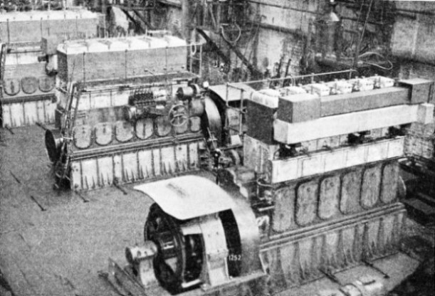
THREE SIX-CYLINDER DIESEL GENERATING SETS on the test bed. The generators are arranged for direct coupling to the engine flywheel and are mounted on an extension of the engine bedplate. The engines are intended for a twin-screw motor vessel and each has a brake horse-power of 600.


 When the power developed is so great as to involve the generation of more heat than can be easily dissipated in this way, the Froude type of hydraulic dynamometer is extensively used. This was invented by the late Dr. William Froude, and is used for all kinds of testing purposes. The hydraulic dynamometer is now often used, even for moderate-
 In more important installations the steam consumption tests may be required not only for full load but also at intermediate loads between full and one-
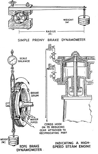 team turbines are almost invariably run condensing, as their efficiency is particularly affected by the degree of vacuum produced by the condenser. The most accurate vacuum gauges are necessary to take the readings in the exhaust from the turbine. A difference of half an inch in the vacuum of a condensing plant of a 10,000-