
© Wonders of World Engineering 2014-


Part 49
Part 49 of Wonders of World Engineering was published on Tuesday 1st February 1938, price 7d.
Part 49 includes a photogravure supplement showing the reclamation of the Zuider Zee. This section illustrates the article on Reclaiming the Zuider Zee.
The Cover
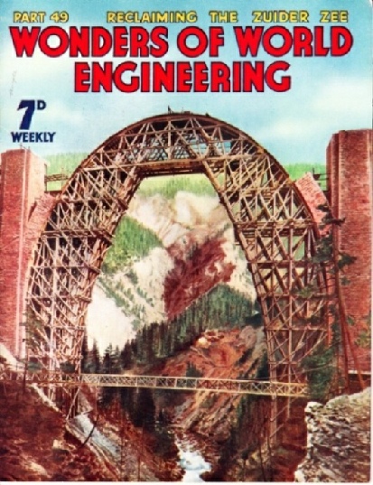
The cover of this week’s Part shows the building of one of the great viaducts of Switzerland. Railway engineering in such a mountainous country is exceedingly difficult, and the great Alpine tunnels are only a few of the major engineering works that have been necessary to establish efficient railway communications in Switzerland. The cover shows the timber falsework erected in the building of one of the arches of the great viaduct near Wiesen, between Davos and Filisur, in the canton of Grisons. The viaduct carries one of the lines of the Rhaetian Railway, which is built to a gauge of one metre (3 ft 3⅜ in). The main arch of the viaduct has a span of 180 feet and is 289 feet above the river.
Contents of Part 49
Alpine Tunnels (Part 2)
Road Engineering
Swimming Pool Machinery
Reclaiming the Zuider Zee
Reclaiming the Zuider Zee (photogravure supplement)
Standards of Accuracy
Canals Across Sweden (Part 1)
Alpine Tunnels (Part 2)
The Mont Cenis, St Gotthard, Simplon and Lotschberg were, at the time of their building, unprecedented triumphs of engineering skill. The four great Alpine tunnels form a group which is unrivalled elsewhere. The work of building these tunnels is described in this chapter.
It is the tenth article in the series Below the Surface. The article is concluded from part 48.
You can read more on the St Gotthard and the Simplon Tunnel in Railway Wonders of the World.
Road Engineering
The heavy motor traffic of to-day demands highways of a type far different from the paved roads built by Roman engineers, or the coach roads built by men such as Telford and McAdam. The making of roads was one of the earliest activities of the engineer. Long before the Romans, some of whose roads are still in use to-day, there were well made roads which bore all the commerce of the time. The roads of Roman days were probably more satisfactory than any of the roads which saw the coming of motor transport. Since that time, however, remarkable improvements in highway construction have been made. This chapter describes how various kinds of roads are built.
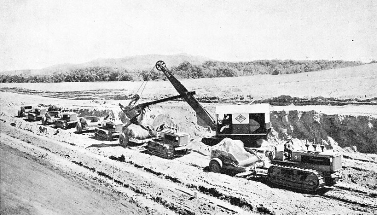
Cutting a Level Road Through a Hill
CUTTING A LEVEL ROAD through a hill. Scrapers are being used as transport trucks to removed the spoil cut away by an excavator. When the cutting is finished the scrapers are formed in line abreast to clear away all the loose material so that a smooth road bed is left for the next operation.
Reclaiming the Zuider Zee: Photogravure Supplement - 2
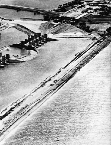
BETWEEN THE IJSELMEER AND THE NORTH SEA is a great dam, eighteen and a half miles long, extending to the coast of Friesland from the island of Wieringen at Den Oever. At the Wieringen end are fifteen great sluices, arranged in three groups of five, and a lock for shipping. The subsidiary dikes, built to facilitate the main work, were later levelled and dredged away.
Standards of Accuracy
Modern engineering demands a high degree of precision, based on accurate measurements, accurate standards of design and dimensions, and an accurate system of gauging. For example, the Imperial Standard Yard is the product of years of experiment. The cornerstone of all modern engineering is accuracy. This, no doubt, seems an obvious statement to make, but in the days of James Watt accuracy was neither expected nor regarded as possible. It is surprising to a modem engineer that the early inventors were able to make any headway at all with the inaccurate methods then in practice. Accuracy in modern engineering is based first of all on accurate measurements.
The Standards Department of the Board of Trade houses the official British standards of length, weight and the like. The establishment of a sufficiently accurate standard of measurement was a matter which for many years exercised the ingenuity of scientists, engineers and legislators, but eventually the Imperial Standard Yard was produced. This now constitutes the standard legal measure of length throughout the British Empire. By comparison with this standard yard the International Prototype Metre, a similar bar housed in Paris measures 39.370147 inches.
If there was one man who did more than any other to introduce absolute accuracy into machine work, that man was Joseph Whitworth. Even before the standard yard was definitely established, Whitworth, in his Manchester workshop, was using apparatus by which he could measure accurately and rapidly to one-millionth part of an inch.
Reclaiming the Zuider Zee
Photogravure Supplement - 3
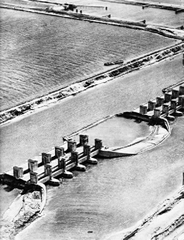
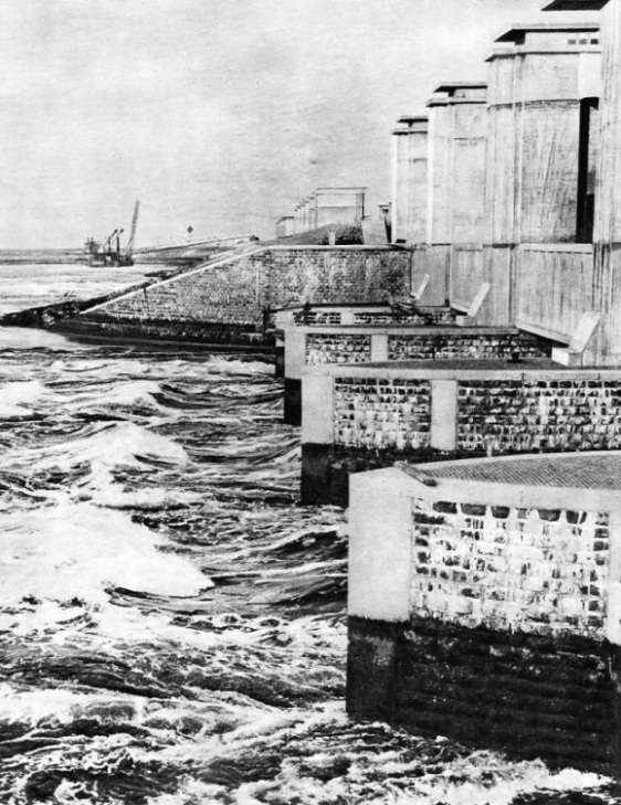
SLUICES AT DEN OEVER, where the main dam joins Wieringen, allow the overflow from the Ijselmeer to discharge into the North Sea at low tide. In addition to the fifteen sluices here, there is a set of ten near the other end of the dam, two and a half miles from the coast of Friesland.
Swimming Pool Machinery
THE space occupied by indoor swimming pools is generally not fully used. In winter swimming pools are often closed. In some instances, attempts are made to remedy this uneconomic use by building up a heavy scaffolding from the bottom of the bath and laying a floor on it flush with the surrounds, so that the whole surface is available as seating accommodation for a concert or as a dance floor. The changeover thus made is, however, a slow and costly process and to cover in such an enormous pool as that in the new exhibition building at Earl’s Court, London, would involve a forest of supports, needing a long time to erect and dismantle and occupying valuable storage space when not in use.
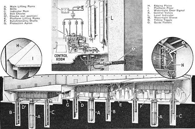
This pool is probably the largest of its kind in the world. It measures 195 feet by 95 feet and occupies a large portion of the central hall. The engineer was, therefore, set to work to design a movable steel floor which could rapidly be raised to the level of the surrounding floor, thus making the whole of the area available for exhibition displays. The lowest illustration below shows the floor at its swimming pool level, that is, with a shallow end, a gradual slope into deep water and a still deeper section for high diving. The floor consists of three sections, each 95 feet by 65 feet and weighing altogether 720 tons. If required, any of the sections can be raised 5 feet above the surrounding floor, to form a large stage. Each section is raised and lowered by two hydraulic rams shown at A. The rams do not carry the floor when it is stationary, the load being then taken on the stilts C. The stilts are formed with projections on either side at the different levels required. The projections bear on pivoted chocks on the solid foundation on which the whole weight is thus carried. The chocks are tilted out of the way to give free passage to the stilts when the floor is being raised or lowered. Steadying rollers and other devices take any lateral stress off the rams.
Movement of the two right-hand sections is carried out when the floors are horizontal; these sections have to be tilted to the correct slope for the bottom of the pool by the small hydraulic rams E. Here again the weight, when the floor is at rest, is not taken by the rams but by the jointed struts N. These function in much the same way as the struts for keeping up the hood of an ordinary perambulator. The steel floor has a granolithic covering (I) to match the floor of the central area and the connexion between the deep section and the others is made by a fold of rubberized canvas G. Sliding connexions are fitted all round the edges of the sections as shown at H in the inset on the left. The rams are controlled from a room below floor level and behind one of the walls of the bath. The work was carried out by the London Hydraulic Power Company.
This is the twenty-third article in the series on Modern Engineering Practice.
(Pages 1394)
You can read about Building a Modern Bathing Pool in Part 26.
Reclaiming the Zuider Zee
One of the largest engineering undertakings of recent times has been the reclamation of the Zuider Zee and the recovery of thousands of acres of land from the North Sea, which centuries ago robbed Holland of much valuable territory. Reclamation work is being carried out in various parts of the world, but the most amazing instance of large-scale reclamation is going on at the present time in the Netherlands. Long ago the Zuider Zee was a prosperous and fertile plain, but in the thirteenth century the North Sea broke through and inundated the plain, leaving only a few islands which were once the hills. For centuries Dutch engineers have fought the encroaching sea, and in this type of work they hold a pre-eminent position.
A dam, eighteen and a half miles long, has been built from Friesland to the island of Wieringen. This dam serves to separate the North Sea from the Zuider Zee, but means had to be provided for giving the waters that formerly fed the Zuider Zee access to the ocean. Accordingly, the land reclaimed from the Zuider Zee is divided up into four polders. Polder is the name given to a tract of land recovered from the sea.
The polders are enclosed by dikes, and between the dikes run drainage channels, connected with a new lake which is called the Ijselmeer. The new lake receives the discharge of the River Ijsel and forms a waterway for ships. These waters escape into the North Sea through sluices in the main dam.
Already one of the polders is completely reclaimed and is flourishing with many kinds of crops. When the whole scheme is completed, Holland will have added to her territory an area almost equal to that of Warwickshire, and sufficient to support a population of 300,000. This reclamation work, which is one of the most important feats of engineering described in Wonders of World Engineering. The chapter is accompanied by a striking section in photogravure.
Reclaiming the Zuider Zee
Photogravure Supplement
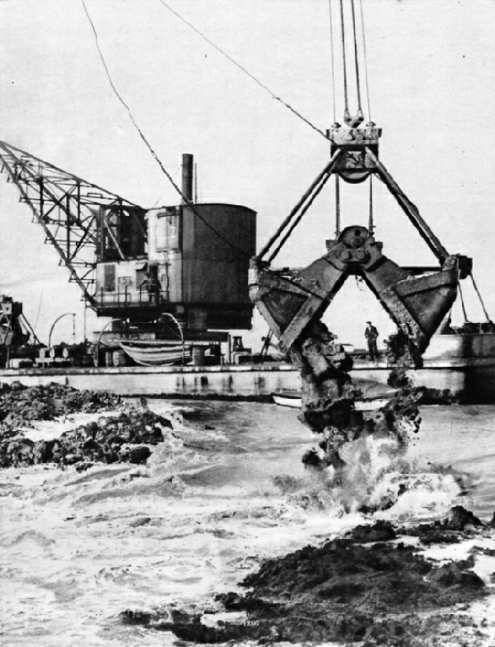
ENORMOUS GRABS, operated by floating cranes, were used to build up the core of the dam from the bottom of the sea by depositing on it stiff boulder clay dredged from the North Sea between the island of Tessel and Harlingen, on the coast of Friesland. The eighteen and a half miles of the main dam were largely built up in this way.
New Locks and Old on the Trollhattan Canal
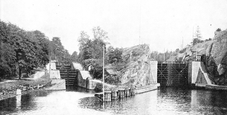
NEW LOCKS AND OLD on the Trollhattan Canal which connects Lake Vanar with the Kattegat at Goteborg. The locks on the canal built by Erik Nordvall and opened in 1800 are 21 feet wide at the gates, but in 1916 new locks were built having a width of 45 feet.
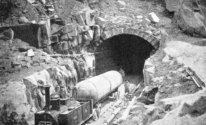
Work at the Entrance to the St Gotthard Tunnel
WORK AT THE ENTRANCE to the St Gotthard Tunnel, which was begun in the autumn of 1872. Its length is about 9¼ miles. Compressed air was used to operate the drills throughout. The headings were enlarged originally to only half the full designed section of the tunnel.
Sweden’s Canals (Part 1)
Despite the natural obstacles to canal building in Sweden, the country is equipped with a fine system of waterways which run inland from Goteborg to Stockholm. Many of the canals were of early origin and for their time were remarkable examples of civil engineering. Sweden is a country which is of the greatest interest to the engineer. Not the least interesting are the canals which have been built at various times between the inland lakes of Sweden and the Baltic Sea. This chapter is concluded in part 50.
You can read about the Gota Canal System in Shipping Wonders of the World.
Testing Standard Gauges for Accuracy
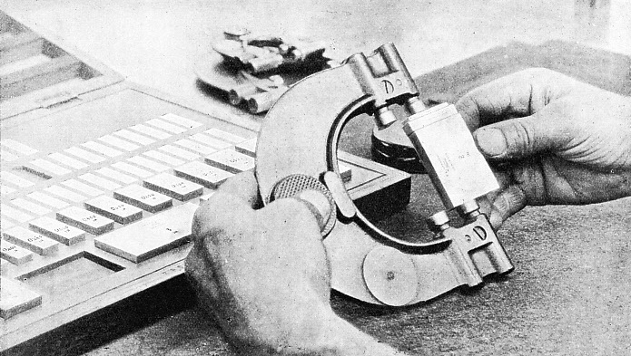
TESTING STANDARD GAUGES for accuracy by Johansson blocks. Invented by a Swedish engineer, Carl Edward Johansson, these metal blocks are within two parts in a million of their nominal size. So accurate are the plane surfaces that two blocks pressed together will adhere, to form a new component having a length equal exactly to the sum of the lengths of each unit. There are three blocks in the gauge illustrated, one of 2 in, one of 0.25 in, and another still smaller.
Building the Main Dam Across the Zuider Zee
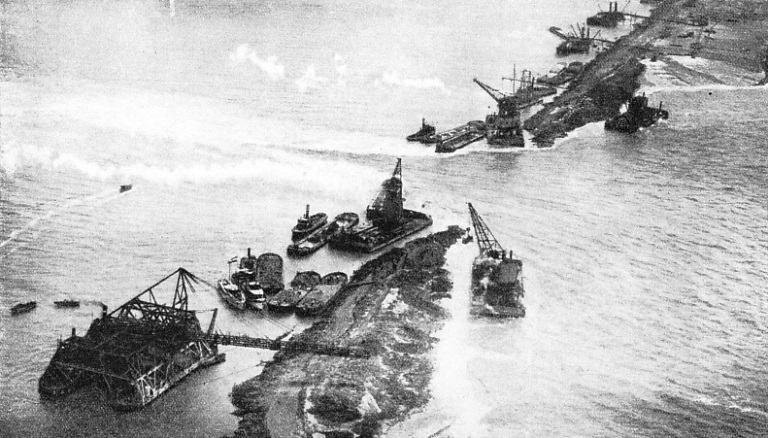
BUILDING THE MAIN DAM across the Zuider Zee, from the island of Wieringen on the west to Friesland on the east. In the foreground a massive floating grab transporter is depositing boulder clay to form the core of the dam and, in the background, sand is being pumped behind the dam to form its inner slope The boulder clay was brought to the spot in barges..
