OF the thousand and one tasks the engineer is set to perform, one, unthought of comparatively few years ago, is that of ensuring the continuity of colour light signalling which is now so familiar a sight on railways. With the old semaphore system lighted at night by oil lamps, a breakdown of any signal caused only a local disturbance, but a current failure when electric colour signals are used might paralyse a whole area.
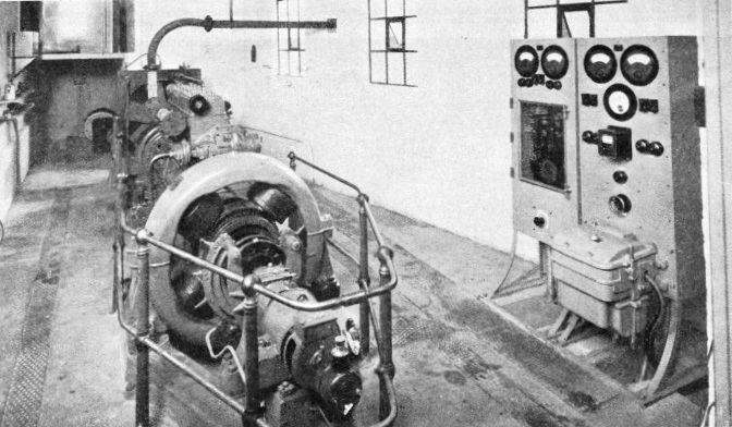
The railways, therefore, have emergency generating sets at strategic points. One of these sets is that illustrated above, which has been installed for the Great Western Railway at Paddington Station by Austinlite Limited. Should an interruption occur in the main current supply, pressure of a button will start up the set, and within ten seconds an equal supply of current is in the circuit. The
current, which is single-phase alternating current at 460 volts, 50 cycles, is generated by the alternator seen in the foreground of the picture, the driving power being supplied by the oil engine immediately behind it.
This engine is a Paxman-Ricardo four-stroke airless-injection diesel engine. It has six cylinders and develops 157 brake horse-power when running at its normal speed of 1,500 revolutions a minute. An oil engine always has to be turned to start it just as a motor car has to be “cranked up”, and in this instance the engine is coupled, on the side away from the alternator, to a motor which is driven by direct current of 60 volts from a 30-cell storage battery. The two panels at the right-hand side of the engine-room effect the automatic control of the set. One of them has starting and stopping push-buttons, and there is a similar pair of buttons for the signalling current in the main transformer station, in which station there is always an operator on duty. Should a current failure take place it is immediately detected by the operator, who actuates the starting push button of the emergency set in the station.
On this action electric devices in the panels complete the storage battery circuit, and the starting motor turns the engine, the fuel valves of which are automatically opened at the same time. The engine then begins to “fire” and quickly reaches its full speed. After this has happened the automatic devices change the winding connexions of the motor, so that it becomes a dynamo and begins to charge the battery, replacing the current that has been used in starting. On the battery becoming fully charged another automatic change is made and the dynamo output is reduced to a “trickle”.
The engine cylinders are water-cooled, the water itself being cooled in a radiator with a fan blowing over it just as in a motor car. The radiator is kept full of water by a ball-cock from an overhead tank; but, should the engine lubrication system fail or the engine be overloaded, the cylinders will heat up above the normal. A thermal relay then comes into action through the electrical gear and cuts off the fuel supply, so that the engine stops and an alarm bell is rung. On the other hand, should the engine-room become so cold that the water in the radiator is likely to freeze, the alarm is sounded. The lubrication of the engine is effected under pressure from a pump. This pressure is also watched and, should it fall below the normal for more than thirty seconds, the engine is automatically stopped.