


© Wonders of World Engineering 2014-


A group of twelve towering masts at Rugby is the outward sign of a modern engineering marvel and a vast radio organization that links Great Britain with ships on the high seas and with every corner of the world.
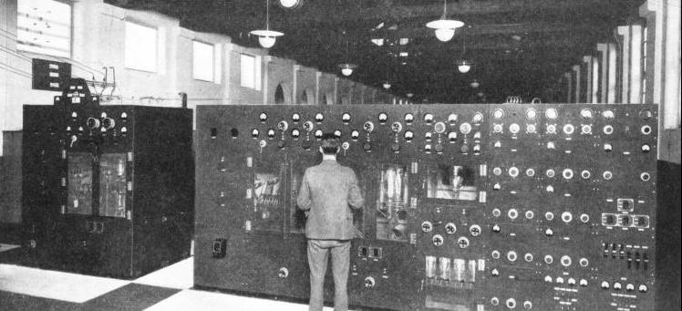
FOR THE CANADIAN SERVICE a 60-kilowatts short-wave transmitter is used. When atmospheric conditions are sufficiently good, the power is reduced to 20 kilowatts. The Canadian transmitter illustrated is typical of the equipment in the short-wave building. The final amplifier (on the left) is used only when the higher power is being radiated.
EVERY traveller from London to Chester, whether he uses the London, Midland and Scottish main line or whether he drives up Watling Street, the Roman road, must be familiar with Rugby - the giant of the ether. He has probably noticed merely a group of towering masts and knows little else about this modern marvel of radio engineering. Possibly he knows vaguely that the masts belong to the GPO Radio Station. Unless he has been conducted over that station he can have no idea of all that Rugby stands for.
In 1924 there were 900 acres of farm land between Hillmorton and Kilsby, two villages a few miles south-east of Rugby. A dozen farm buildings, a few trees and a decrepit barn or so were the only landmarks. On January 1, 1926, the Rugby Radio Station began work, and twelve 820-feet masts, their tops sometimes invisible in the clouds, formed the chief outward sign of change. Beneath the masts the station buildings. large as they are, appear insignificant.
To-day the same 900 acres are covered with aerials of every conceivable type - a veritable network of wire - and the station is housed in two separate buildings. Ten different transmitters handle between them almost every long-distance telephone call that is made between Great Britain and the rest of the world. If you speak to a friend on board the Queen Mary from your home, your voice is radiated from Rugby; and through the same station you may talk to North and South America, Africa, Japan, India, Australia or Iceland. Ships at sea compile their daily Press Bulletins from news received direct from Rugby.
Rugby was originally designed as a high-powered radio station which would provide reliable telegraphic communication of world-wide range throughout the whole of the twenty-four hours, no matter if conditions were good or bad, and with equal efficacy by day or night.
Press news, messages to British ships at sea and private communications were to be handled. At the time of the original conception of the station the short waves had not been proved as a reliable means of communication, and thus Rugby was designed essentially as a long-wave station, working on the wavelength of 18,750 metres.
This choice of wavelength was responsible for the building of an aerial nearly two miles long and over 750 feet. high, and the use of higher power than had previously been approached by any radio station in the world.
The site near Rugby was chosen because of the absence of hilly or wooded country and road-crossings, and because it was 340 feet above sea level and conveniently situated for London, Birmingham and other large towns and cities. There are few parts of the country in which the main aerial could be erected without obstructions of any kind.
The design provided for an aerial suspended on sixteen masts, but only twelve were built. These, however, were so placed that four more could be added when necessary. Calculations and estimates showed that reasonable efficiency, coupled with economical construction, could be obtained with masts 820 feet in height, 70 feet of sag being allowed for at the centre of each span of the aerial.
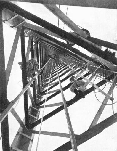
That statement convoys nothing whatever of the engineering feat involved. Each of these masts weighs about 200 tons, stands on a porcelain insulator, houses an electrically-driven lift capable of carrying three people, and has to stand a horizontal strain of some 10 tons at the top, due to the weight of the aerial.
The masts are of lattice steel construction, in the form of a triangle with 10 feet sides. They do not taper, but the scale of the members is decreased at each of the five points to which the stays are attached. These stays, of which there are fifteen to each mast, are anchored to huge blocks of concrete deeply embedded in the ground. Each stay consists of 150 wires, not wound into a cable, but laid parallel and bound together. Each stay is nearly as thick as a man’s wrist.
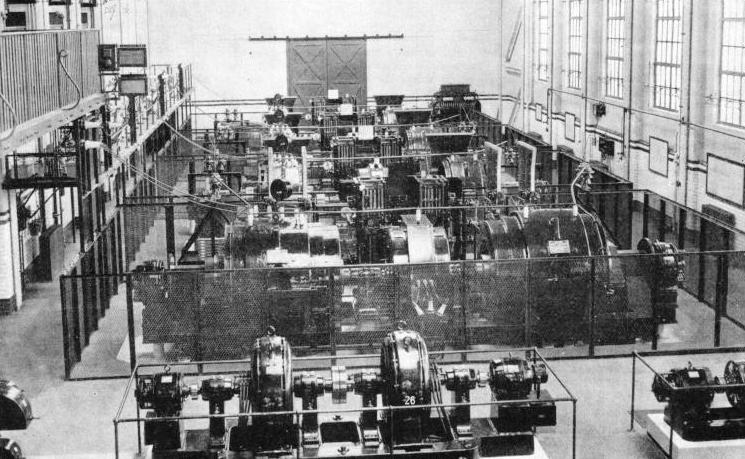
THE GENERATORS FOR THE LONG-WAVE TRANSMITTERS are housed in the power room in the main building. The four large units in the photograph give an output of 500 kilowatts each; three operate at 6,000 volts and one at 12,000 volts. The smaller units in the foreground each generates 200 kilowatts for low-tension filament current. An elaborate system of safeguarding is enforced for the protection of the apparatus and of the staff. The dangerous high-voltage leads are taken to control points well out of reach from which they are taken through the wall, straight to the transmitters in the adjacent main hall.
Near the foot of each mast, about 30 feet from the ground, is a platform carrying two winches driven by large electric motors. One of these winches carries the halyard for the aerial, and the other operates the lift inside the mast.
A ladder inside the mast is also provided for emergency use, but the emergency would need to be acute before one would make use of it. An ascent by lift takes nearly twenty minutes, and it is possible to climb from the lift, by means of a short ladder, on to the top platform of the mast.
While one is ascending by the lift, surrounded by the metalwork of the mast, no electrical effects are noticed, but on the open platform at the top everything is “live” when the big transmitter is in operation. One can draw sparks from the brads in one’s shoes, and it is easy to read the Morse keying of the transmitter by this means.
The aerials, which look insignificant from the ground, are of enormous dimensions. “Sausage” construction is used, six or eight wires being spread out to a diameter of 12 feet by steel spreaders. Huge insulators and guard rings, which have to be inspected at frequent intervals, connect the aerials to the halyards which pass down the centre of the mast.
Sparking in Bad Weather
IT is impossible to describe the sensation of height that one obtains from the top of the masts, unless one compares it with that of looking down from an aeroplane. Certainly no high building will give it. These masts are more than twice the height of St. Paul’s Cathedral (355 feet), but a mere ten feet in diameter.
The large aerial which they support is used only for the long-wave transmissions, and is led into the station through the centre of a window 7 feet square by means of a copper tube some 20 feet in length. In the early stages of operation, the wooden frame round this window began to char and burn when the transmitter was switched on. Precautions were taken to avoid this, an earthed guard ring being fitted round the window.
New difficulties then arose with flashing over (unwanted sparking) in bad weather, and now a huge cowl protects the lead-in from the weather. The charring of the window-frames and the possibility of flashing over at such a distance give some idea of the enormous power fed into the aerial. The normal working value of the aerial voltage is about 165,000.
 The earth system consists of over 200 miles of buried wire laid out underneath the main aerial. The wires are 50 feet apart, and are buried a few inches below the ground. The transmitter feeding this aerial and earth system is the most powerful telegraphy transmitter in the world. When it was built it was the only transmitter of its class designed for use with valves, all the others operating with arcs or alternators.
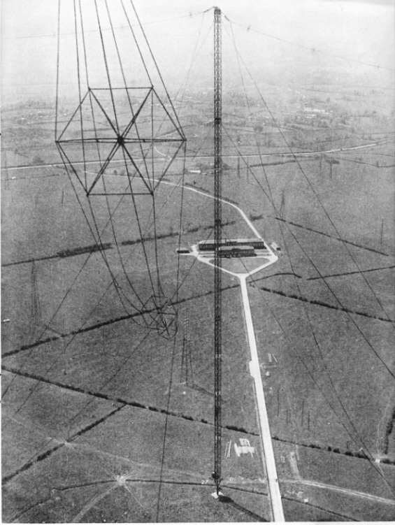
THE VIEW FROM A MAST at Rugby gives a vivid impression of the spaciousness of the site. The 820-feet mast seen in the foreground is a quarter of a mile distant from the mast where the photograph was taken. Twelve of these masts are used to support the long-wave aerials. Eight of them are arranged in the form of an octagon, with a further four to the north. Each mast weighs some 200 tons, and stands on a porcelain insulator.
News bulletins are broadcast daily to the Empire and to British ships at sea in all parts of the world; radio-telegrams handed in at any Post Office are transmitted all over the world: and time signals, direct from Greenwich Observatory, are broadcast twice daily for astronomical and navigational purposes, with an accuracy of 1/100th of a second.
All this is the work of G B R, which is the highest-powered long-wave transmitter in the world, and has remained virtually unchanged since 1926. The tuning coils of the G B R transmitter arc wound on hexagonal “spiders” roughly 8 feet in diameter and are mounted high up in the roof of the main building. They are wound with Litz (stranded and specially insulated) wire of 6,561 strands, each insulated from its neighbours. The combined wire, which is externally bound with insulation, is more than one inch thick. These coils resemble the “basket” coils that were used so frequently in the early broadcast receivers. Viewed from the floor of the station. 60 feet below, they can be seen to swing as the current flowing round them is “keyed” by the Morse transmitter.
Each of the three main power units uses eighteen valves of the most powerful type which was available when the transmitter was built. They are each rated at 10 kilowatts (equivalent to approximately 13 horse-power), and operate with a voltage of 12,000 on their anodes, which are water-cooled. Some fifty gallons a minute pass through each of the three units. The cooling water is taken from specially-built ponds in the station grounds. Two other units are installed, and it is intended, later, to use a single 500-kilowatts valve in one of them. This valve is at present in the experimental stage, and is of the demountable type. In other words, if its filament burns out, the whole thing can be taken to pieces, refitted and evacuated again by pumps permanently installed for the purpose. When it is finally working. this single valve will be capable of handling the entire output of G B R, the long-wave station.
The power for this and for the other transmitters is generated on the premises by motor generators, which are installed in a separate part of the building. Four high-tension generators are rated at an output of 500 kilowatts each, three of them giving this output at 6,000 volts and one at 12,000 volts. The generators for the low-tension filament, current. have an output of 200 kilowatts, and in the same engine-house are more than a score of smaller generators for other purposes, including grid-bias.
The big transmitters for G B R stand in an orderly row in the main transmitting hall, which is isolated from the generating-room.
Nerve Centre of the Transmitter
A HIGH standard of safeguarding is enforced, for the protection of the staff and of the apparatus. It is quite impossible for an unauthorized person to get within reach of a “live” part of the transmitter, and the staff themselves cannot possibly make adjustments until everything is completely “dead”. These precautions are essential.
The power unit cannot be connected to the high-vol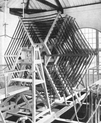 tage supply until all the, metal gates at the sides of the units have been locked, and their keys locked into the operating switch itself. These keys, for opening the gates, are not released until the switch which earths all parts of the power unit has been operated.
 tage supply until all the, metal gates at the sides of the units have been locked, and their keys locked into the operating switch itself. These keys, for opening the gates, are not released until the switch which earths all parts of the power unit has been operated.
 All this work is carried out in the main station building, which is perhaps the most impressive part of Rugby because of the spectacular nature of the high powers used, and also because of the enormous dimensions of the aerial system. Two short-
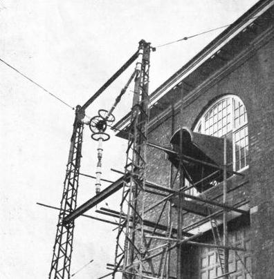 f one is blessed with an acute sense of direction, one may wander round the field at Rugby and hazard intelligent guesses at the parts of the world to which the various aerials are directed. Because of the deceptive nature of maps on Mercator’s projection, however, the Japanese, Indian and Australian beams take a far more northerly path than one would imagine. Only by looking at a good globe can one realize that the beam to Australia is projected roughly in the direction of Sweden, and that that for Japan takes an even more northerly path.