


© Wonders of World Engineering 2014-


The power of the wind is one of the forces of nature that man from time immemorial has harnessed in various ways. Modern developments from the various types of windmill are used for driving ships, for pumping water and for generating electricity
 TWO of the great forces of Nature which the engineer has subdued for the use of man are wind and water. The origins of windmills and watermills are lost in antiquity, but it is probable that the windmill was developed first in Europe after the watermill. It was not until the middle of the thirteenth century that windmills were such common features of the English landscape that they became the subject of artistic representations.
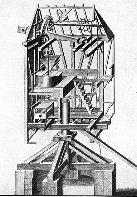
The earliest mills are of the type known as the post mill. A box-
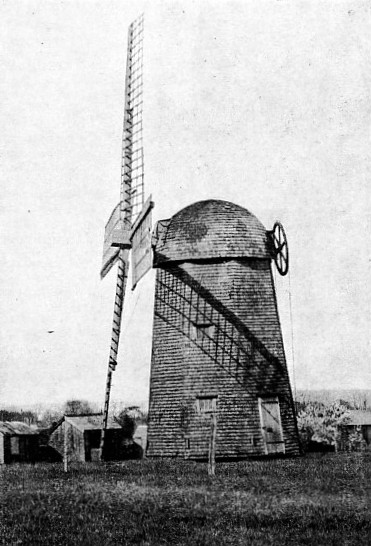
FIXED TO THE CAP of this windmill near Newport, Rhode Island, U.S.A., is a large pulley connected to a geared rack fixed to the top of the tower. This wheel is operated by an endless chain from the ground. Thus the cap and the sails are easily turned into the eye of the wind.
The post passes through the lower floor of the mill body and fits into the socket of a horizontal beam or “crowntree”, which rests on top of the post. The whole body of the mill is built up from this crowntree, and these timbers, generally of oak, are large. A size of 2 feet square is commonly found in a crowntree, and in a post at its base. Crosstrees and quarter bars are often 12 in. Square.
To steady the body of the mill and take some of the side thrust due to the wind, a bearing known as the collar is fitted to the post at the point where it passes through the bottom floor of the mill. At first the substructure of the mill was open to the weather, and a few examples are still to be found. Later the substructure was enclosed with a “roundhouse” of brick or timber, which protected it from the weather and formed a useful store.
The oldest and probably the smallest post mill in England is that at Bourn, in Cambridgeshire. It was standing in 1636 and has been bought and repaired by the Cambridge Preservation Society. The oldest working windmill in England is the post mill at Outwood, in Surrey, built in 1665. The largest and most modern examples of post mills in England are to be found in Suffolk, a county which also contains the majority of working post mills.
Some post mills were built with the whole of the substructure buried in the ground, presumably to make the mill less liable to be blown over in a gale, for the crosstrees of the ordinary post mills merely rest on the piers and are not fixed to them in any way. Examples of these “sunk post mills” still exist in Sweden and the remains of several have been found in England, as at Sandon Mount, Hertfordshire.
Most inventions are the result of an attempt to save labour, and so it was with the development of the windmill. The miller found that considerable effort was required to start to push the post mill round when the wind changed, and in the Netherlands a new type of mill known as the “hollow post” mill was developed. The mill body was small, all the machinery was placed in a fixed building below the substructure, and the drive from the sails was taken down through the post itself, which formed a hollow tube.
An improvement on this type of mill was developed in Holland probably in the sixteenth century. The building containing the machinery became a tower with a small movable head or “cap” on the top, carrying the sails. This is even easier to turn than the
hollow post null and is much simpler. The cap runs on rollers or blocks on a well-
Smock mills were probably introduced into England by the Netherlanders, who came over to drain the Fens at the beginning of the seventeenth century. The largest and finest English smock mill is to be seen at Cranbrook, Kent, where it was built in 1814.
Lincolnshire and Norfolk have the largest number of working tower mills in England, as well as the most modern and up to date. The largest existing English tower mill is at Sutton, in Norfolk; larger tower mills have disappeared. The largest was Southtown Mill, Yarmouth. It was about 120 feet high and was demolished in 1905.
In addition to such mills, yet another type is to be found in the Netherlands, Germany and possibly elsewhere. The wooden mill body carries a circular track on its base and its brick foundation has a similar track on top. Between the two tracks is an independent ring of rollers, and on these the whole mill can be turned round. This type of mill is known as the “paltrok”, and was developed during the seventeenth century. In the Netherlands it has always been used for sawmills, but only a few examples are left to-
To work at maximum efficiency the sails of a windmill must always face square into the “eye of the wind”. The post mill has a long pole, known as the “tailpole”, fastened to the back of the mill under the bottom floor, passing through the ladder and projecting outwards and downwards well clear of it. Normally the bottom of the ladder rests on the ground and acts as a back stay to support the mill against the force of the wind.
When the wind shifts round and the mill has to be turned, the ladder is raised off the ground by a lever on the tailpole connected to the ladder with a chain and held in position with an iron pin. Once the ladder has been raised the mill is turned by pushing the tailpole, which occasionally has a wheel fixed to its end and sometimes rests in a crutch when the mill is at rest. If the mill is well balanced and the sacks of meal and grain are evenly distributed in the mill, the turning is an easy matter once the inertia has been overcome.
Turning Sails to the Wind
 An alternative to this method of turning the mill is to set a ring of small posts round the mill. A portable winch is hitched to a post and its chain is run out and fastened to the tailpole of the mill. On winding in the chain the tailpole is moved towards the winch and the mill is turned. Tower mills also have tailpoles for turning their caps, and the winch is used for this purpose. An improvement was to fix the winch to the tailpole itself, and this method is still commonly used in the Netherlands to-
SECTION OF A POST MILL, as illustrated in Diderot’s Encyclopaedia, published in the eighteenth century. The earliest mills were of this type, machinery and sails being supported by and pivoting on a central post. In this diagram the sails are not shown.
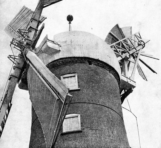
A natural development was to place the winch inside the cap of the tower mill, connecting it by gearing to a toothed rack fixed to the curb. A variation of this is to place the winch on the outside of the cap and to operate it by means of an endless chain hanging down to the ground.
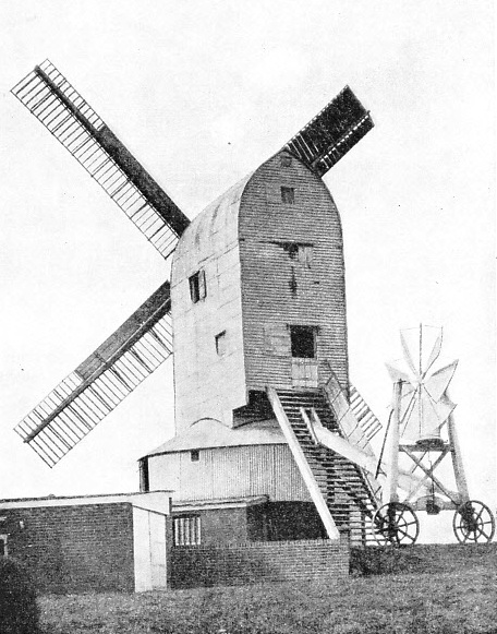
In 1750 Andrew Meikle, a Scottish millwright, inventor of the threshing machine, invented the automatic “fantail” for turning mills into the wind. This fantail is in effect a small windmill consisting of a number of inclined vanes on a horizontal spindle, which is fixed at right angles to the “windshaft” on which the sails are mounted. So long as the sails are square in the wind’s eye, the vanes of the fantail present only an edge to the wind and remain stationary. When the wind veers round it strikes one side or the other of the vanes and causes the fan to turn. Set at the tail of a tower mill cap, the fan is connected by gearing to a rack on top of the mill tower, and continues to turn the cap until the sails are once more square into the wind’s eye and the vanes of the fan are again presenting an edge to the wind.
Fantails are applied also to post mills. In a few they are set at the rear of the roof ridge and drive down either to a worm wheel fixed to the post below the bottom floor of the mill body, or to the wheels at the bottom of the ladder, running on a track round the mill. Sometimes the fantail is supported on a special carriage fixed to the tailpole. The most usual method, however, found principally in East Anglia, is to cut off the tailpole where it passes through the ladder, to mount the fan on a carriage at the rear of the ladder and to gear it to wheels at the bottom.
Setting Sail Cloths
The sails of early windmills consisted of a flat framework inclined at an angle to the normal — generally about 17° — on which the sail cloths were spread. The cloths, generally two to a sail, were threaded in and out of horizontal bars forming the framework of the sail, and were set by pulling out sideways from the centre as one would pull a curtain.
These sails were improved by giving them a twist or “weather”, as in a propeller, and by spreading the cloth on top of the sail frame on the rear or driving side only. On the front or “leading” side a narrow leading board is substituted for the sail frame, being placed at a constant angle to the normal, ideally 22½°. The cloths are set with cords known as “pointing lines” to sword point, dagger point, first reef, and full sail — technical but self-
In Sweden the constant angle type of sail, instead of being cloth-
All these sails are wooden frameworks built of bars and laths on a stout backbone or “whip”. Through the end of the windshaft, which carries the sails, are passed two larger timbers, or “stocks”, at right angles to each other. Each of these, stocks has a pair of sails bolted and clamped to it, and sometimes in addition wooden side clamps are used, connecting the whips of two opposite sails.
 In 1775 Andrew Meikle invented his “spring sail”. For the cloths of the common sail he substituted a number of hinged shutters connected together by a “shutter bar”. By this means all the shutters in a sail can be opened or closed at the same time, as in a Venetian blind. The bar is connected to a spring, whose tension can be varied by adjusting mechanism at the tip of the sail. Thus if the mill is not to work, the shutters of each sail are opened in turn and the mill is said to be “sailed out”. If a mill is to work, the shutters are closed and the springs are adjusted according to the power required.
THE AUTOMATIC FANTAIL, introduced by Andrew Meikle in 1750, is a small windmill set at right angles to the plane of the sails. When the sails are square in the wind’s eye, the vanes of the fantail, presenting only an edge to the wind, remain stationary. When the wind veers, it turns the vanes of the fantail, which, being connected to the cap by gearing, automatically turns the sails into the wind again. The photograph is of Cross-
The shutters are made of wood or of wire frameworks filled with canvas. The sail is said to he double-
When a mill with spring sails is at work the shutters open and “spill the wind” as soon as the wind pressure is sufficient to overcome the spring tension. Then, as each sail comes to the lowest position, the shutters will close, often with a clap which sends a shower of raindrops against the body of the mill in wet weather. Although these spring sails are self-
In 1809 Sir William Cubitt improved on the spring sail by connecting together the shutter bars of each sail to a spider coupling at the centre by means of bell-
On the same spindle as the pinion he mounted a chain wheel from which an endless chain hung down. By pulling the chain the chain wheel was turned, moving the pinion, the rack, the striking rod in the shaft, the spider coupling, cranks, rods, and finally the shutters, the total effect being similar to the opening and closing of an umbrella.
To hold the shutters open, a weight is hung on one side of the chain; to hold them closed it is hung on the other side. Adjustment can also be varied according to the power required before the wind strengthens sufficiently, opens the shutters and blows through. Thus all the sails can be regulated at the same time without stopping the mill.
This type of sail has always been known in England as the “patent sail”. Its mechanism has been improved by the substitution of a rocking lever for the chain wheel to which the striking chain is hung; but although favoured in Denmark and Germany, it is not used to any extent elsewhere on the Continent. In England, however, but for the fantail and patent sails few of the two hundred working windmills would have survived.
Eight-
In France the Berton sail is still to be found. This resembles a parallel ruler made of a number of thin strips of wood which will open out to form a sail or close up on top of the whip and present a small area to the wind. These sails are not automatic, but can be operated simultaneously without stopping the mill. They necessarily form a flat plane when open, and hence are inefficient, but are simple to build and repair. In Lincolnshire and the East Midlands, as well as in Anglesey and the north-
The size of sails is limited by their weight. Were they increased in length too much, their component members would have to be increased to such a size as to make them economically ineffective. If the number of sails is increased the power obtained is not increased in proportion, as the correct air flow is interfered with and the efficiency of each sail falls.
 In the ’sixties of last century several mills in England were fitted with annular sails having a large number of shutters set in them, and operated in much the same way as patent sails. The only survivor, now derelict, is that at Haverhill, in Suffolk. This mill has a sail, fifty feet in diameter, fitted with 120 shutters, five feet long and a foot wide.
PATENT SAILS of Penny Hill Mill, near Holbeach, Lincolnshire — a six-
The latter half of the nineteenth century saw the production of the American windmill, used principally for pumping water. This type consists of a large number of straight wooden blades of small width assembled in narrow sections and held by truss rods at an angle to the normal, the whole forming a wheel. The wind, striking the blades, turns the wheel as in the automatic fantail from which it is derived. Two main varieties of wheel are used. In the first variety a windvane projects behind the wheel, and keeps the wheel to the wind. The governor is centrifugal and causes sections in the wheel to pivot and present a greater or lesser surface to the wind. The second variety has a vane directly behind the wheel and nearly in the same plane. The sections of the wheel are fixed and, as the wind varies, the pressure on the governor vane causes the whole wheel to turn out of the eye of the wind. Thus the surface presented to the wind is varied, and the speed remains constant.
Two variations of this method are used. The first is to place the windvane at a slight angle to the centre line of the wheel shaft. The wheel is never truly in the eye of the wind, and as the pressure of the wind increases the vane is forced farther to the side and the wheel is moved out of the wind. The second variation is to fix the axis of the wheel slightly out of centre with the pivot on which it turns to face the wind. As the wind increases the wheel is turned out of the eye of the wind and this movement is controlled by a horizontal tension spring, attached to the windvane, which tends to hold the wheel into the wind. A third method is to have no windvane at all, but to rely on the pressure of the wind on the wheel to bring it in to the proper direction.
Uses of Streamlining
The early wheels have been improved by substituting a few light curved sheetmetal vanes for the large number of heavy straight wooden slats, and by working their pumps through a 2½ to 1 reduction gear instead of using a direct ratio drive. The recent introduction of ball and roller bearings and gears running in oil has still further increased efficiency.
In recent years much attention has been paid to the production of windmills with streamlined sails for the generation of electricity. The Burne windmill is a pioneer in this respect. It has aerofoil sails of orthodox appearance, but of theoretically correct design. Each sail is divided longitudinally, and as the wind velocity increases the sails fold backwards, thus deflecting the wind pressure and increasing the resistance to rotation.
Other mills have a small number of vanes, generally from two to six, similar in appearance to the blades of an aircraft propeller and covered with metal or fabric. In the “Aerodynamo”, designed by Major Bilau, small fins of aerofoil section are mounted, one in front and one behind each of the four blades. As the speed increases, the fins gradually open by centrifugal action, increasing the resistance of the blade and tending to keep its speed constant. By mounting the wheel behind the supporting structure, the disturbance to streamline flow is reduced and no windvane is required.
 Probably the largest windmill of this kind is at Balaklava, in Russia, where a large three-
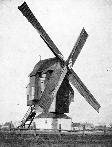
POST MILL NEAR CALAIS, FRANCE, with sails consisting of cloth spread across a light framework. These were the earliest types of sail, known in England as common sails. A great advance in design was made in 1775 when Andrew Meikle introduced his spring sails, composed of shutters controlled by springs.
The many varieties of windmills so far described are of the “vertical” type — that is to say, they have sails revolving in a vertical plane on a horizontal axis. There is also an entirely different type of windmill, having sails revolving in a horizontal plane on a vertical axis. This type is known as the “horizontal” mill. Such mills are still to be found in the East. Those found in Seistan, Iran, where the wind blows from the same quarter for almost the whole year, consist of tall vertical poles, with reed-
In the Gulf of Chihli, in China, the mills are placed in the open. The vertical pole carries radial frames, in which the sails are pivoted vertically in such a way that, when turning against the wind, they swing round in their frames and present only an edge to it, but, turning with the wind, they present their whole surface. They are used for raising water by means of a chain of pots for the production of salt by evaporation. In Tibet small mills are used to turn prayer wheels.
Windmills of one sort or another are to be found in almost every corner of the world, ranging from the homemade mills, which rattle a pebble in a tin to scare the crows, to the highly developed electrical generator in Russia. That corn grinding was the first function of vertical windmills can be seen plainly from their design; but water raising must have been an early application also, and it is probable that the hollow post mill owes its development to the need for land drainage in Holland.
Sawing wood by wind power was first carried out in the Netherlands at the end of the sixteenth century, and later became common. Lacking water power, the Netherlands developed the uses of wind power to an amazing extent. Mills pressing oil from linseed, grinding cocoa and snuff, hulling rice and making paper were all to be found at one time in considerable numbers.
Application to Ships
An important development of wind power occurred in 1923. In that year, in Germany, Anton Flettner filed his patent for assisting the propulsion of ships by making use of the “Magnus effect”, produced by a rotating cylinder. Thus the rotor ship was born. The rotors are smooth, vertical cylinders with wide flanges at the top and bottom. They are driven by a low horsepower motor. Flettner designed his rotors to act as auxiliaries to a powered ship, the object being to save expense by making use of the force of the wind.
To quote Flettner himself: “In the rotor sail the wind velocity is reduced on the side of the rotor where its surface turns in a direction opposed to the wind, and on this side the atmospheric pressure increases. On the other side, where the rotor moves in the same direction as the wind, the wind velocity is increased and the atmospheric pressure materially decreased. Pressure on one side and suction on the other produce a thrust which pushes the ship ahead.”
When the wind is blowing at more than twenty miles an hour, the forces acting on the rotor do not increase, and the power obtained depends on the peripheral speed of the rotor.
In Finland Savonius has produced a “wing rotor”, which consists of a rotor split in two with the halves offset and a free air passage between them; in section they resemble a letter S which has been cut in halves, the lower half being raised a little. The wind, striking the inside of one half, is deflected and caused to strike the inside of the other half, and the resulting force rotates the rotor, no initial rotation being required. This form of rotor has proved satisfactory for pumping and other purposes.
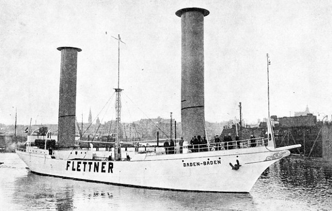
THE FIRST ROTOR SHIP appeared in 1924. She was the Baden-
You can read more on “How Grain Cargoes are Handled”, “The Milling of Flour” and “Power and the Plough” on this website.
You can read more on “Rotor Ships” in Shipping Wonders of the World