Pumped through a great pipe line, water for the gold-bearing district of Kalgoorlie is brought across parched land from a reservoir in the Darling Range, 350 miles away
MUNDARING WEIR was built across the Helena River about twenty-eight miles from Perth, the capital of Western Australia, to form a reservoir for the supply of water to the Kalgoorlie district. Eight pumping stations force the water along the pipe line to the goldfield area.
The Mundaring to Kalgoorlie Water Supply Works in Western Australia, which were completed in January 1903, rank among the greatest achievements of engineering. Water is gathered in the Darling Range, near Perth, the capital of Western Australia, and is forced by eight pumping stations to the goldfields about 350 miles away. It is raised more than 1,200 feet in the process.
There are more than 1,500 miles of main and subsidiary pipes. Farms, towns and mines hundreds of miles distant depend for their existence mainly on the water which is pumped through what was formerly a wilderness.
The success of a boldly conceived and splendidly executed scheme has enabled the mineral wealth and the agricultural resources of an area of 16,000 square miles to be developed. The whole scheme is a noteworthy example of how men engaged in various branches of engineering have combined to defeat Nature and have enabled miner, farmer and townsman to flourish in what was, almost within living memory, a blank space on the map of Australia.
Gold was the magnet which drew adventurous men from the coastal fringe of Western Australia to the extraordinary plateau which lies about 350 miles from the west coast and some 250 miles from the south coast. On this plateau, which is some 1,300 feet above sea level, they found gold, but little water. The rainfall varies from 3½ in. to 9 in. a year, but the rain was of little use to the gold-seekers, as it was swallowed by the thirsty earth and contaminated by the salt that lies below the surface.
The wandering aboriginals guarded the secrets of the location of the “soaks” — places where drinkable water could be found by digging in the sand or in holes in the rock — but Government engineers searched and found the places where water existed.
Even then the water was poor and there was not enough of it. The gold-seekers were at first gold-diggers, not miners. The first gold discovered lay on the surface. One of the two men who discovered the Coolgardie goldfield stumbled over a stone, looked at it, and saw that it was a nugget.
The early diggers overcame the lack of water by processing the pay-dirt by a process called dry-blowing. They let the mixture of dirt and gold drop from one pan to another underneath it, and the almost constant wind blew away the light dust and did not deflect the heavier gold dust. Only when they had winnowed the dross from the gold by repetitions of this process did they make use of the precious water. Later, rich veins under the earth were located near what is now Kalgoorlie. To crush the quartz in mills and batteries required machinery and water. Government engineers searched for water as assiduously as the miners searched for gold, but the engineers could not locate enough water. Almost on the heels of the prospectors, the railway followed them to the goldfields, and new towns began to spring up.
The engineers bored wells, condensation plants were built to distil drinkable water from the salt water obtained from the wells, water was brought by rail, and cement-lined reservoirs were built to catch the infrequent rain. Hundreds of thousands of pounds were spent, but it was obvious that the whole area could not be made to yield sufficient water at an economic price, and also that, apart from money considerations, the health of the thousands of people who had flocked into the area was endangered by the shortage and by the poor quality of the water.
Many schemes were considered, and it was finally decided that the only adequate solution of the problem was to bring the water more than 300 miles from the Darling Range. It was decided to dam the Helena River, a tributary of the Swan River upon
which Perth stands. The catchment area of 569 square miles has an average yearly rainfall of 30 in., and the yearly inflow into the reservoir has varied from 300 million to 41,000 million gallons. The watershed is thickly timbered with jarrah, red gum and wandoo (white gum) trees.
After nearly a score of sites had been inspected it was decided to build the dam at Mundaring, about twenty-eight miles from Perth. The surface area of the reservoir is 672 acres and the capacity is 4,650 million gallons.
Foundations in River Bed
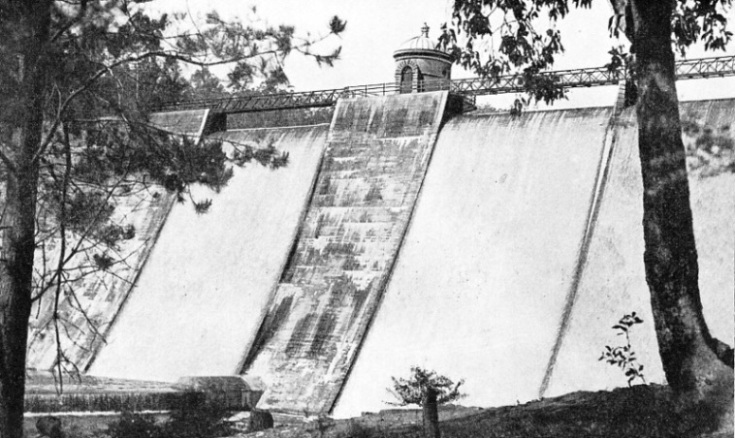
The huge concrete overflow weir which dams the Helena River is 755 feet long and tapers from a thickness of 11 feet at the crest to 85 feet at the bottom. The greatest depth of water is 100 feet at the wall, and the length of the reservoir is about seven miles. About 82,000 cubic yards of concrete were used to build the weir.
A tower gives access to valves for drawing off the water at various levels, and at the foot of the wall is a scour valve for removing silt. The weir is built at the point where the river is penned in a rock-bound gorge, and the river bed was excavated to secure solid rock for the foundations.
Since the completion of the weir in 1903 there has almost always been enough rain in the catchment area to cause the water to top the summit of the wall, sometimes by as much as 2 feet. In 1914, however, the rain was exceptionally slight and the water did not overflow in that year.
Three pipes are arranged at levels of 20 feet, 47 feet and 74 feet above the bed of the river to draw off the water from the reservoir and carry it to a common standpipe, which was built in a well in the wall of the weir. From the standpipe the water passes out at the same level as the lowest of the three inlet pipes to two outlet pipes, which traverse the weir to a point where they converge into a single pipe. This pipe carries the water to the first pumping station, which is on the north bank of the Helena River, about a quarter of a mile wrest of the reservoir.
THE CONCRETE WEIR which dams the Helena River tapers from a thickness of 11 feet at the crest to 85 feet at the bottom. The weir is 755 feet long and contains about 82,000 cubic yards of concrete.
The scour pipe is placed 10 feet above the bed of the river and, leading from the reservoir, follows the two outlet pipes and joins the single outlet pipe below the junction, with a branch pipe to discharge into the river. There are two sets of valves to control the pipes. One set is operated from the tower on the wall of the weir; the other is controlled from a similar structure placed a little way downstream, just below the junction of the main pipe and the scour pipe.
After having reached the first pumping station the water is pumped up 410 feet into a 500,000-gallons concrete tank situated a mile and a half away, at the second pumping station. The second station pumps the water up another 370 feet through thirty-five miles of pipe to a 1,000,000-gallons concrete tank at West Northam, from which it gravitates to the third pumping station at Cunderdin, seventy-six miles from the second station.
Over the next stage of sixty-two miles the water is raised 290 feet by the pumps at No. 3 Station to the 1,000,000-gallons concrete tank at the fourth station near Merredin. From No. 4 Station the water is lifted 396 feet through thirty-three miles of pipe to two tanks, each holding 1,000,000 gallons, at No. 5 Pumping Station near Carrabin.
At No. 5 Pumping Station the water is lifted 161 feet through forty-six miles of main to a 1,000,000-gallons tank at No. 6 Pumping Station at Ghooli, about eight miles east of the town of Southern Cross. The sixth station pumps the water a distance of thirty-two miles and lifts it 187 feet to a 1,000,000-gallons tank at the seventh station near Gilgai. This station lifts the water 179 feet into a tank a mile and a half away at Koorarawalyee; this tank holds 1,250,000 gallons.
The water gravitates from this tank past No. 8 Pumping Station into a 2,000,000-gallons concrete tank situated on Mount Charlotte at Kalgoorlie, through nearly ninety-nine miles of pipe. No. 8 Pumping Station, near Dedari, is forty-five miles from the seventh station, and is used as a standby. The pumps are put into operation when the demand for water at Kalgoorlie is more than the main will carry by gravitation from the Koorarawalyee tank or when the Bullabulling Reservoir, between the- eighth station and Kalgoorlie, needs more water.
351 Miles of 30-in. Pipe
The total length of main pipe from the first pumping station to the tank on Mount Charlotte at Kalgoorlie is 3491 miles. To this must be added a branch main pipe half a mile long to a stand-by reservoir of 10,000,000 gallons at No. 3 Pumping Station, and another branch main pipe of one mile to the 12,000,000 gallons stand-by reservoir at Bullabulling, so that the total length is 351 miles. There are eleven other storage tanks along the route, with a total capacity of over 17,000,000 gallons. There are also branch main pipes, some of them many miles in length, which supply towns, mines and farm lands.
The engines installed at the pumping stations were horizontal triple-expansion direct-acting pumping engines of 350 indicated horse-power, the stroke being 36 in. Three sets of engines and pumps were installed at each of the stations from No. 1 to No. 4, and two sets at each of the other four stations.
The greater part of the original cost of the scheme was expended on the 351 miles of 30-in. diameter steel conduit pipe. The pipe line was built of pipes made of a standard length of 28 feet and jointed by a patent “locking bar” system. The pipes were of 5/16-in. and ¼-in. plates curved to a radius of 15 in. and held together by locking bars on either side.
This form of pipe was made of semicircular steel plates fastened together along their edges with two longitudinal locking bars of soft steel, the flanges of which were pressed on the edges of the plates until a tight joint was made. There was no riveting, nor were there any overlapping plates.
A TOWER ON THE MUNDARING DAM houses the valves tor drawing off the water from the reservoir at various levels. Three pipes are arranged 20 feet, 47 feet and 74 feet above the bed of the river to draw off the water and carry it to a common standpipe built in a well in the wall of the weir.
The making of the pipes, which included the cutting to correct length and width, the dovetailing of the edges, the curving to the required radius and the squeezing on of the locking bars by hydraulic pressure, was done with the metal cold. This work, with the curving and welding of the joint rings, was carried out locally. The pipes and joint rings were heated and immersed in a bath of pipe coating. After having been dipped the pipes were placed in a revolving machine and sand was applied to the outside coating.
Transport and the route of the pipe line were made easy by the presence of the railway. Ordinary railway wagons, with special superstructures, carried eight pipes and rings. About a dozen wagons made a trainload and the trains were sent out and unloaded on the site. As the pipe line was placed alongside the railway for the greater part of its length little cartage was required.
The joints of the main conduit were caulked by a machine which fitted round the pipe in two halves. The rims of the machine, which held the caulking tools, were turned by gears driven by an electric motor. The electricity for this was generated by a dynamo operated by a 5½ horse-power oil engine, the generator and the engine being mounted on a wheeled frame.
The cable for carrying the current was reeled on a drum attached to the caulking machine and comprising a quarter of a mile of cable, so that, by moving the generator in advance, half a mile of pipes could be caulked before the generator had to be moved. The caulking machine transport was wheeled along the tops of the pipes from joint to joint, and each machine required four men to work and move it. As the locking bar projections prevented the caulking tools of the machine from working right round the pipe, two men worked ahead of the machine caulking round the bars by hand.
Water at 2s. 6d. a Gallon
Originally the pipe line was laid for the greater part of the distance in a trench with a covering of 2 ft. 6 in. Where the pipe line crossed a salt lake the pipes were supported above the ground by piers. In the course of years external corrosion began, and a great part of the pipe line was uncovered and placed on wooden blocks free of the soil and left uncovered. Rust formed inside the pipe line and impeded the flow of water, so that the pumps had to work beyond their designed capacity to force the water through.
After investigation by experts, who found that the chief cause of the internal corrosion was the oxygen dissolved in the water, new methods were introduced to remedy this trouble. A de-aerator was installed at the first pumping station to treat the water
after it had been drawn from the reservoir and before it reached the pumps.
Air vessels on the pumps were altered to prevent the water from absorbing air during pumping and to keep air from entering the pipe line when pumping ceased. Tanks were built at the summit of each section to keep the pipe line full of water when the pumps were not working.
Completion of the scheme was a great boon. In the pioneer days people paid as much as 2s. 6d. a gallon for water. When conditions improved salt water was sold at 25s. a thousand gallons and condensed water at about £5 a thousand gallons. When the pipe line reached Kalgoorlie the water was sold at 7s. a thousand gallons to the municipalities, and at 6s. to the mines and the railways. With the improvements in water conservation made locally, the supply to the thirsty lands was so abundant that it was possible to tap the Mundaring Reservoir to increase the supply to the eastern part of Perth. Originally the sum of £2,500,000 was raised in London to finance the undertaking, but this estimate was exceeded. The original loan was redeemed by the sinking fund, and up to date the capital cost has been more than £4,000,000.
RETAINED BY MUNDARING DAM, the water has a surface area of about 672 acres. The reservoir is about seven miles long and has a capacity of 4,650 million gallons. The catchment area of 569 square miles has an average yearly rainfall of 30 in.