An outstanding feature of the Cape to Cairo route is the great bridge which spans the gorge of the Zambezi River below the Victoria Falls in the heart of Africa. The bridge was built in Great Britain and assembled at the site
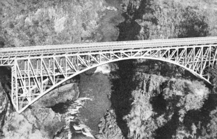
A SINGLE-SPAN STEEL ARCH BRIDGE crosses the Zambezi River where it runs through a deep ravine below the Victoria Falls. The bridge was built to carry the railway across the Zambezi and the railway reached this spot in May 1904. In 1930 the deck was raised 5 feet and widened 13 feet to accommodate a motor road.
CAPE to Cairo by railway - that was the dream of Cecil Rhodes, the pioneer who gave his name to the vast African region of Rhodesia. The railway runs from Capetown to the northern border of Rhodesia, and thence into Belgian Congo. Steamer services on the African lakes and rivers partly span the ensuing gap before the railways of the Sudan and of Egypt are reached.
The way was barred by the mighty Zambezi River, and over it the steel highway had to be carried. Shortly before his death in 1902 Cecil Rhodes himself chose the crossing place for the railway, within sight of the stupendous Victoria Falls, within reach of their spray. David Livingstone discovered the Falls in 1855, exactly half a century before the spanning of the river.
Surely no other bridge is set amid such scenery as this remote spot in the heart of Africa. At this place the mile-wide Zambezi plunges thunderously over a cliff 400 feet high, throwing clouds of spray to a height of 3,000 feet. Opposite the snow-white of the foaming waterfall another towering cliff forms the farther wall of a vast trench a mile long and over a hundred yards wide. It is this amazing geological formation that produces the immense clouds of spray, forced upwards from the depths to fall in a never-ceasing shower on the cliff top. The Zambezi, broken by its awe-inspiring plunge, swirls and eddies in a raging torrent between the black, rocky cliffs of a marvellous zigzag gorge.
Across that narrow gap, between the dark, towering cliffs of the gorge facing the giant wall of white falling water, there is now a slender arch of steel. Such is the setting of the bridge at Victoria Falls, a triumph of human endeavour and engineering skill.
The survey of the bridge site was made during the Boer War of 1899-1902, and in May 1903 the contract was let, despite keen foreign competition, to a British concern, the Cleveland Bridge and Engineering Company, of Darlington, Co. Durham. The firm was destined, thirty years later, to build yet another bridge across the Zambezi, the Lower Zambezi Bridge at Sena, Mozambique, with a total length of two and three quarter miles.
It had been agreed that the preliminary work should be undertaken by the railway company which anticipated that the track from the south would have reached the Falls by the end of 1903. Because of unforeseen difficulties, however, the railway did not reach the site until May 1904, so that until then it was impossible to transport any bridge building material. The railway company’s part in the undertaking comprised the transport of materials from Great Britain to the Zambezi, the building of quarters for the workmen and the excavations necessary for the foundations.
It was intended that the ends of the bridge span should rest on ledges cut in the solid rock on either side of the gorge. On the north bank the rock proved to be solid and the excavation was a comparatively simple matter. The surveyor’s impression of conditions across the water, however, were based on far less reliable evidence. The apparently solid rock, after the tangle of tropical vegetation had been cleared away, proved to be a mass of big boulders and loose debris held in a giant cup in the solid rock of the south cliff. By the time the railway company had made this discovery the preparation of the steelwork in England had reached a stage when alteration of the design was impracticable.
There was no alternative but to deal with the problem and get down to rock bottom. The difficulty was tackled boldly by laying bare the solid rock of the cliff and facing the lower part of the mass of debris with a great fill, or wall of concrete. The height of the south abutment was further increased by the use of deeper concrete foundations.
Despite these measures, however, it was found necessary to lower the whole bridge 21 feet below its intended level; and cuttings for the railway track were necessary on either side of the gorge.
The Victoria Falls bridge was designed by George Andrew Hobson, MInstCE, of the firm of Sir Douglas Fox and Partners, the consulting engineers. Mr. Hobson was assisted by Mr. Ralph Freeman who, a quarter of a century later, was to design the great single arch bridge over Sydney Harbour. Among considerations that had to be borne in mind was, first, an appearance that would blend with the natural beauty of the site. Then followed the more material problems of rigidity, to permit railway traffic, economy in building to keep within the limits of the contract and, finally, a method of building that dispensed altogether with scaffolding.
A single-span steel arch was chosen as meeting all requirements. This is of the two-hinged type with its four “feet” hinged to steel bearings in the concrete abutments. The whole structure may be compared with two gigantic sword blades curving upwards, with hilts on one side of the mighty gap and points embedded in the opposite rocky wall. As the fierce African sun blazes down the steelwork of the great arch expands and lifts slightly, turning on its hinged bearings, but at the same time retaining its rigidity without buckling or becoming distorted.
Cliff 400 Feet High
The analogy of the swords is not complete, because the bridge is of the braced spandrel type; that is to say, there is an approximately horizontal top chord that is linked by verticals to the lower chord or arc. The panels so formed are braced diagonally and thus the top chord, carrying the load, relieves the arc of some of the stress. This type of bridge is one of the easiest to erect and every part assists in the building of the whole structure.
The bridge site is about 700 yards below the cataract and the top width of the gorge at this point is 650 feet. The height from the cliff top to the water is about 400 feet. The great central arched span of. the bridge is flanked by two straight spans of braced girders 12 ft 6 in deep, divided into square panels and spaced 20 feet apart. The span on the north or left bank is 62 ft 6 in; that on the south bank measures 87 ft 6 in. From the centres of the bearings on opposite sides of the gorge the central arched span measures 500 feet, with a rise of 90 feet. There are twenty panels each 25 feet long. A panel comprises the space enclosed by two uprights and their diagonal, giving the appearance of a letter N. The depth of the arch girder at the crown is 15 feet and at the ends or abutments 105 feet.
A SAFETY NET was slung across the gorge to prevent workmen from falling to certain death during the building of the Victoria Falls Bridge. Not a single workman, however, fell from the bridge during the work.
The upper ends of the main girders of the arch are inclined inwards; they measure 27 ft 6 in between their centres at the top and 53 ft 9 in at the bottom. The members of the arch or ribs (the swords in the analogy) are farther apart at the abutments than at the centre of the bridge. Because of this tapering the hinges are not set square with the ribs but with the longitudinal centre line of the bridge structure.
How the Weight is Borne
The ribs consist of hollow steel girders, about 3 feet square in section. Each girder ends in a solid steel forging that rests on a steel saddle over a bearing pin on the foundation pedestal. The pins have a diameter of 12 in and are 5 ft 10 in long. They were made from solid steel forgings, accurately turned all over and drilled through the centre to accommodate an anchoring bolt. The lower extremities of the end posts terminate in steel forgings similar to those of the ribs. Rib and end-post forgings at their respective corners are united by bent plates and diaphragms and by the common saddles resting on the bearing pins.
Each of the four bearing pins is carried in a forged steel cup, machined and fitted to the top of a pedestal, built up of six triangular plates bolted to a heavy base plate. This base plate is composed of seven steel beams and is secured to the sloping concrete foundations by four large bolts. The saddle and cup round the bearing pin are held together by end plates and the anchoring bolt. This arrangement permits the saddle to move slightly round the bearing pin but not to lift from it. The calculated thrust on each of the four bearings is 1,600 tons.
Every part of this bridge was first built in Darlington. Ail joints were carefully planed and the various members of the 25-feet panels were specified to vary not more than in. from their designed length. The vertical girders were secured to the upper chords and arcs by steel pins weighing only 30 lb to facilitate handling. The pins were fitted with a temporary screwed cone at one end to allow easy threading through the holes in the girder plates that they were intended to join together. The arch girders on either side of the bridge are joined together by two systems of wind bracing. One set of bracing girders is arranged immediately under the cross girders that carry the deck of the bridge and the other girder system unites the two adjacent sides of the arch ribs.
Vertical bracing in the form of an X was also arranged between verticals on opposite sides of the bridge, and at various points there are numbers of horizontal transverse girders. Among these the most important are the strong lattice girders, 6 feet deep, that unite the end posts and carry the fixed ends of the shore spans. The outer ends of the shore spans rest on roller bearings so that they, and the main structure to which they are attached, shall be free to expand or contract under the influence of temperature changes.
When all the steelwork had been completed at Darlington it was erected in the company’s yard to ensure that every component was perfect. The whole bridge was not erected, but all panels were tried in place and the central portion was temporarily built up “on its back”. Then, with all sections complete and numbered, the load of 1,500 tons of steelwork began its long journey to the Victoria Falls.
THE BRACED SPANDREL TYPE of bridge construction was used for the Victoria Falls Bridge. The structure consists of an approximately horizontal top chord linked by verticals to the lower arc. The panels formed by the verticals are braced diagonally.
The remoteness of the bridge site contributed a large share to the difficulties of the builders. Here was a spot in the heart of Africa, 3,000 feet above the level of the sea, abounding in wild animals and providing no facilities in the form of native labour. Before the coming of the railway no native would live within sixty miles of the Falls for sheer superstitious dread. At that distance the spray can be seen, and nowhere within ten miles of the tumbling waters is one beyond earshot of their deafening roar. The lead given by the white man, however, overcame native fears and at one time there were 400 natives working on the bridge.
The first practical problem was the crossing of the gorge. About three miles above the Falls it is possible to cross the Zambezi by boat, despite the hippopotami and crocodiles. There was, however, more to be done than the building of the bridge. The railway, it was decided, must be pushed forward simultaneously at the rate of at least a mile a day. This necessitated the daily transport of some 200 tons of material for the track alone.
As early as July 1903 tenders were invited for a cableway to span 870 feet, well over the limits of the gorge and capable of carrying a load of 10 tons a trip. It was arranged that the bridge builders should have a prior right to the use of the cable. This cableway was a marvel of ingenuity, and materials for it were unloaded at the Zambezi in June 1904. The cable weighed 5 tons, and consisted of nineteen steel wires surrounding a hemp core, with a circumference of 8½ in and a breaking strain of 270 tons. That cable had to be flung across the gorge, 650 feet wide. First, a rocket was shot over the chasm, carrying a light cord to watchers on the opposite cliff. The cord was then used to haul across a wire attached in turn to a light rope. A traveller or carrier, carrying the end of the main cable, was then rigged on the rope and hauled across the gorge by a second rope and a winch.
Spanned by a Cableway
On one bank the cable was attached to a steel tower 36 feet high, anchored at the rear with guy ropes. On the opposite bank the cable was attached to the top of a pair of sheer-legs, 80 feet long, hinged to massive foundation plates embedded in concrete. The sheer-legs were arranged to lean away from the gorge at an angle of 45 degrees, and from the top of this enormous jib was suspended a counterweight of 60 tons. The conveyer resembled the crab of a travelling crane, and was used for raising and lowering the loads, as well as for running along the cable. It was operated electrically, carrying its own driver and power lines from a generating station on the cliff top.
In working conditions the counterweight balanced the tension of the cable. As the loaded conveyer from the farther end approached the middle of the gorge the centre of the cable became lowered and the weight was raised. After the load had passed the centre of the cable the weight was automatically lowered and the cable raised, providing a reduced incline for the conveyer, which thus required less power to drive it for the remainder of its journey. Despite many difficulties the cable and conveyer lasted just for the duration of the job, although a new cable and conveyer had been made to act as a stand-by.
All the material for the northern half of the bridge was duly carried along the cable in loads of 10 tons and, by the same means, were transported many miles of rails, thousands of sleepers, quantities of stores, contractors’ locomotives and wagons, some 15,000 tons in all. The special cradles designed for conveying sleepers along the cable made popular transport cars for the workmen. When the atmosphere was highly charged with electricity the conveyer would sometimes be enveloped, high over the gorge, in a blaze of lightning.
Work on the concrete foundations for the main bearings of the bridge was begun in May and was finished in October 1904. The concrete was reinforced with old rails and steel rods, and was allowed to mature for six weeks to ensure proper hardening. The cement was sent out from London packed in iron drums, and it arrived at Victoria Falls in perfect condition.
ACROSS THE ZAMBEZI GORGE the steelwork of the bridge was advanced from either bank. When anchorages, vertical end posts and shore spans had been completed, electric cranes were mounted on the cross-girders to facilitate the handling of the steelwork. The cranes were specially designed with double jibs, each with a radius of 30 feet and a capacity of 10 tons.
The bearing sites were first of all surveyed and the distance between them, across the gorge, was worked out by triangulation. To check the mathematical calculations, however, a distance of 500 feet was marked off by two posts on level ground near the bridge site. Then a length of wire was suspended between the posts and its tension recorded on a spring balance. The wire was then marked at the posts, and one end was hauled across the gorge. When the same tension was applied to the marked wire, it was a simple matter to determine the limits of 500 feet across the water in a straight line.
The erection of the shore spans of the bridge was begun in August 1904. The ends of the spans were placed in recesses in the rock on either side of the gorge, and were anchored by their upper corners. The spans were built out on scaffolding assisted by the anchorage, and this work on the steep and rocky cliff side proved to be a task of great difficulty and danger. Meanwhile the concrete foundations for the main bearings had been prepared to receive the bearing base plate.
The top of the concrete foundation was strengthened with steel joists placed transversely to the joists of the base plate. The four holding-down bolts for each base plate had a diameter of 3 in, and were embedded in the concrete. To permit slight final adjustment of the base plate, the bolts were fitted into tubes with a diameter of 4½ in. When, with the utmost care, the steel bearings had been adjusted with all pins in perfect alinement, the whole bearing area was filled with liquid cement under pressure.
Building the Panels
The next job was the erection of the great end posts with their massive transverse girders that support the outer ends of the shore spans. From these end posts the panels were built out over the ravine. Then came one of the most remarkable phases of the work. The great posts, 105 feet long, hinged at their lower ends, were secured to the cliff on either side only by the temp-orary anchorages of the shore spans. The building up of panel after panel towards their meeting place in mid air would have caused the tearing of the shore spans from their temporary anchorages with a headlong plunge by end posts, spans and posts into the swirling waters of the Zambezi far below.
Anchorages had to be provided, therefore, for the two pairs of end posts on either side of the gorge. This part of the work was anticipated and the preparation of the anchorages was undertaken at the same time as the building of the main foundations.
At some distance behind each end post the engineers dug a shaft about 30 feet deep, and on either bank the shafts were joined at the bottom by a short tunnel. Large numbers of steel wire ropes were threaded through these great Us cut in the solid rock and the ends of all ropes were fitted with screwed sockets. The ropes were attached by U-shaped bolts, and their sockets, to 7-in diameter pins in the top of the end posts on either bank. By the adjustment of the nuts on the U-bolts of one rope at a time, the tension on the posts was capable of variation within close limits.
THE VICTORIA FALLS BRIDGE is only about 700 yards downstream from the famous Falls which were discovered by Livingstone in 1855. The bridge was completed exactly fifty years later, in 1905. The falls, about one mile wide and nearly 400 feet high, inspired such awe in the natives that none would live within sixty miles of the spot, until the white man overcame their fears.
With end posts, anchorages and shore spans completed, electric cranes were mounted on the cross-girders for the rapid handling of the panels. The cranes were specially designed for the job and had double jibs, each with a radius of 30 feet and capable of lifting a load of 10 tons. This stage of the work was reached in December 1904.
Below the steelwork as it grew out over the Zambezi, was stretched a safety net which, however, the workmen complained made them feel nervous. But not one man fell into the net during the whole of the work.
Once begun, the task of building the panels progressed at a surprising speed and on April 1, 1905, the ends of the two cantilever arms met in mid air. On that day also another engineering link was brought to success when the headings of the famous Simplon Tunnel met deep within a Swiss mountain.
The perfection of the engineering work in the Victoria Falls Bridge may be judged from the fact that when the centre panels of the arch had been completed at sunset on March 31, the ends overlapped by 1¼ in. This was because the span had elongated after a whole day beneath the fierce African sun. When work was resumed at sunrise the following morning it was found that the span had contracted during the night by 1¼ in and the ends met with mathematical precision. At this stage, however, the bridge was not ready for its finishing touches. It had become what is known as a three-hinged arch with the main hinges at the feet and the third or top hinge at the meeting of the arch ribs. There was thus at this stage no strain whatever in the top chord of the bridge.
ONE OF THE FOUR ANCHORAGES on which the feet of the single-span arch rest. The foot of the arch and the foot of the vertical end post are united by a bent plate and diaphragms and by the common saddle resting on the bearing pin. The bearing pin is carried in a forged steel cup fitted to the top of a pedestal bolted to the base plate, which measures 11 ft 6 in by 5 ft 10 in. The base plate reduced the load on the concrete support to 21 tons to the square foot.
The designer intended, however, that the arch should be hinged at the feet only. To ensure that the top chord should do its fair share of work in carrying trains over the Zambezi, the abutting ends were forced apart by hydraulic jacks for a carefully calculated distance. Steel plates were then secured in the gap and the giant “sword” stood firmly upon its great bearings subject to nothing further that man could do to it, yielding only to the temperature changes imposed by Nature.
On the completion of this portion of the work, including the final riveting of all joints initially held together by the 30-lb pins, the temporary cable anchorages of the spans were removed. The double railway track was laid on baulks of timber resting in longitudinal steel troughs secured to the deck cross-girders. The remainder of the deck was built of creosoted pine planks 9 in wide and 3 in thick, with ½-in air spaces between them. To protect the planking from the heat of the sun and from risk of fire from burning cinders, a layer of Stockholm tar was applied and later strewn with fine gravel and sand. This was, however, found unsatisfactory and the deck was later given a coating of cement.
To-day the Victoria Falls Hotel, run by the Rhodesian Railways, is the centre of a large tourist traffic drawn by the lure of the great waterfall. Changing conditions have also led to alterations to the bridge. In 1930 the deck was raised by 5 feet and widened by 13 feet. A fine motor road, too, now flanks the track of the railway.
Despite the changes that were to take place during the quarter of a century that separated the old deck from the new, the work of the bridge builders was destined to influence even greater feats of engineering. The methods used in the building of the Victoria Falls Bridge were followed in erecting the far larger structures that span Sydney Harbour in Australia and the River Sabi in Southern Rhodesia.


 The perfection of the engineering work in the Victoria Falls Bridge may be judged from the fact that when the centre panels of the arch had been completed at sunset on March 31, the ends overlapped by 1¼ in. This was because the span had elongated after a whole day beneath the fierce African sun. When work was resumed at sunrise the following morning it was found that the span had contracted during the night by 1¼ in and the ends met with mathematical precision. At this stage, however, the bridge was not ready for its finishing touches. It had become what is known as a three-