More than a thousand million passengers are carried by tramway cars in one year in London alone. The trolley bus is replacing the tramway car in many places, but the two systems of transport are of great importance in most cities and towns
EXPERIMENTAL TRAMWAY CAR built by the Glasgow Corporation Transport Department in an effort to produce an ideal vehicle incorporating all modern refinements. The seating capacity is sixty-five, and the car has a length of 34 feet and a width of 7 ft. 4 in.
THE tramway car and the trolley bus are two alternatives to omnibuses driven by petrol or oil engines. In many countries the trolley bus is beginning to take the place of the tramway car, but the tramway car is such an important factor in road passenger transport that it is unlikely to disappear for many years. The vehicle has passed through many stages of development, and the change from horse-drawn to electric tramway cars, even in a great city such as London, is remembered by middle-aged people. Steam cars, cars driven by compressed air and cable-cars, however, have helped to bridge the gap between the horse and the electric motor.
During the period when the horse was disappearing from the tramway, the petrol motor bus was replacing the horse-drawn omnibus. The period that followed — when the tramway car and the motor bus shared between them the burden of public street transport — has now passed, notably in London, where the trolley bus is making great progress, but the electric tramway car is a highly efficient vehicle. In London, during the year 1934-35, more than 1,013 million passengers were carried and more than 101 million service car miles were run.
Tramways began as rails at collieries, along which trucks were pulled by horses, late in the eighteenth century. The first passenger tramway was operated in New York in 1832, and nearly thirty years elapsed before an American, George Francis Train, came to England to introduce the system. The first rails were laid at Birkenhead in 1860, and in the following year tramway cars were introduced to London near the Marble Arch, but the lines were soon taken away because of objections to them. Lines were laid later, however, in Liverpool, London, Glasgow and elsewhere, and horse-drawn tramway cars were developed.
Then various methods of mechanical traction were devised, among them being the cable system, which proved successful in hilly cities and was widely adopted. In London it was used at Highgate Hill and at Brixton Hill. A steam engine hauled a continuous wire rope which travelled in a slot in the road; a steel arm attached to the tramway car and operated by the driver gripped the cable, and by this means the car was hauled along. Meanwhile the electric tramway pioneers were busy, and in 1884 the first electric tramway was installed at Kansas City, U.S.A. Seven years later, in 1891, the first electric tramway in Great Britain was established at Leeds, Yorkshire.
At first, the cars were supplied with current by the trolley or overhead wire system. Then, to avoid the obstruction and unsightliness of the poles and the wires they supported, underground conduit and surface-contact stud systems were introduced as alternatives. In Great Britain the London County Council developed the conduit system until it became the largest of its type in the world.
The evolution of the electric tramway car was of great benefit to a variety of industries, and the change from horses to electricity involved the building of power stations and substations. It helped to cheapen the cost of power and made the public electrically minded. The making of cables, rails, tramway cars and their equipment involved the spending of millions of pounds. The engineering and mechanical equipment was so vast that years elapsed before the electric tramway was to be seen in every town of any size in Great Britain. There were delays because of legislative and financial complications caused by questions of road maintenance and similar matters. Further complications were caused by the fact that some of the tramways were owned by companies and others by municipalities. Thus the British tramways are found to vary considerably in the efficiency of the services and in the size, type and comfort of the vehicles.
The most extensive method of supplying current is the overhead wire system. The current is picked up either by a revolving wheel or by a bow mounted at the end of a tubular pole fitted to the top of the tramway car. The current travels down the copper lead inside the pole to the motors, of which there are generally two. The return current passes along the rails, copper connexions being fitted at the joints of the rails to ensure good conductivity.
Overhead & Underground Collectors
In the underground conduit system the current is collected by what is known as a plough. The plough makes contact with the conductor rails, which are carried in a conduit built below the surface of the road and in the middle of the track. The middle part of the plough is only about ½-in. thick, as it has to travel along a slot in the road which is some ¾-in. wide. At the lower end of the plough are t.wo blocks, which are pressed by a spring against the positive and negative rails. The current passes through one cable in the plough to the motors and returns through another cable in the plough to the second block, which makes contact with the return rail of the system.
In London the inner ring of services uses the conduit system, and the outer the overhead system. At one time the vehicles on one system could not proceed on the other, so that at the junctions of the two systems inconvenience and delay to passengers were caused. Later, vehicles were built with ploughs and with trolleys, so that the transition of a vehicle from one system to another could be made without delay. Tramways are prohibited in Central London. This ban restricted the services until 1906, when they were brought nearer by the laying of the tramway along the Victoria Embankment. In 1906-8 the roadway under Kingsway was tunnelled for single-deck cars, and it was enlarged for double-deck cars in 1930-31 (for which see the chapter “Subterranean London”).
MOTOR SHOP in the London Transport works at Charlton, London. Here the motors of London’s tramway cars are inspected and repaired. After reassembly they are tested by an hour’s run on light load in either direction of rotation before they are replaced on their trucks and put back into service. Just before the transition from tramway car to trolley bus began, London Transport controlled 324 route miles of tramways.
As the intention in London is to replace the tramway car by the trolley bus, no new types are there being put into service. Tramway designing is not stagnant in other cities. Glasgow, which has been referred to as the “spiritual home of the tramway”, has long been noted for the efficiency and enterprise of its services. Two experimental cars built by the Glasgow Corporation Transport Department incorporate the most recent advances in efficiency, attractiveness and comfort. They are of the double-decked type operated by the overhead system, and are 34 feet long and 7 ft. 4 in. wide. They seat sixty-four passengers under cover.
Every effort has been made by the designers to overcome difficulties and to provide the ideal vehicle. The two vehicles vary in some details. The first has two equal wheel bogies, sprung by long laminated axle-box springs. Vibration and noise are two evils with which designers have to contend. To stop small vibrations from reaching the body of the vehicle, heavy section rubber shock absorbers are used. These rubber pads are arranged so that they will deflect in a transverse direction when the car is entering a curve. When the vehicle is accelerating or braking they deflect in a longitudinal direction and help to ensure smooth running and to reduce noise.
Gear wheels are subjected to heavy overloads caused by electric braking, and road shocks caused when the vehicle is passing over points. To reduce these effects, resilient gear wheels of special type are used. The resilient members of each wheel can be replaced without removing the wheel from the axle. The wheels are in two parts: an outer rim with inward projections and a centre part with radial arms. Projections on both parts are provided with holes. to accommodate the resilient members, so that when the wheel is assembled any load transmitted has to pass through these members.
Electro-Pneumatic Control Gear
Motor suspension bars and springs are mounted on rubber, and all flooring has rubber sheeting between it and the steel underframe, which is welded between the headstocks. Platform members are bolted for easy replacement in the event of a collision.
To facilitate cleaning, the windows are rounded at the corners. Floors, platforms and steps are laid with rubber and have rubber wearing strips on top. The entrance steps are closed by twin folding double doors, the one at the fore end remaining shut, that at the rear being open when the vehicle is moving. The throw-over gear by which the seats are reversed at the end of the journey is entirely enclosed. Roof gutters of rubber are connected to down pipes, and holes draining water from the floor of the upper saloon are covered on the outside by cowls. A feature of the upper saloon is the armour plate glass panels on either side of the roof, to give better lighting in daytime. Current from the overhead wire is collected by a bow, which is the standard practice in Glasgow.
IN THE PAINT SHOP at Charlton Works. There are two tracks, each of which accommodates six cars and extends into a drying chamber with room for six more cars. The cars are washed down and given one coat of paint and one of varnish. The double-tier scaffolding enables men to work on the two decks simultaneously.
A 35 horse-power motor is mounted on each axle, and the control gear is electro - pneumatic. This equipment, which is housed in the lower saloon, is virtually noiseless. The controller is small, and the physical effort required from the driver is reduced to a minimum. The gear is designed to reduce the burning of contacts. Should the power from the overhead line fail, a battery is used to energize the control circuit, so that the switches can be operated to work the braking. This battery is charged by the current taken by the compressor motor. Each bogie is fitted with a pair of track magnets, each capable of a vertical pull of 5,000 lb.
Braking is the same as on the standard cars, compressed air and magnetic systems being used, with the addition of an air track brake. The air brake cylinders are mounted on the bogie and the reservoirs are housed under the stair on one platform. The compressor is underslung on the underframe in the centre of the vehicle, and is of the four-stroke slow-speed type. All piping is of copper. The interlocking is arranged so that the two air brakes cannot be applied at the same time. The service brake is the air wheel brake, which must be exhausted before the air track brake can be applied. The air track brake and the magnetic brake are operated by the controller handle. There is also a hand or mechanical brake for parking purposes. At either end of the vehicle is an emergency brake valve which can be applied by the conductor. It operates the track brake irrespective of the position of the controller handle, and to serve this device an auxiliary reservoir is kept at maximum pressure, whatever the pressure in the main reservoir.
Total seating capacity is 65, there being 27 seats in the lower saloon and 38 in the upper. Both saloons are heated by tubular heaters. Eight roof ventilators in the upper saloon are arranged to operate whichever way the car is proceeding. To ensure ventilation in conditions such as a traffic jam in the centre of the city on a hot day, four fans connected in series and fitted in ducts are arranged to provide a maximum of one change of air every minute. Two types of lighting are fitted. That in the lower saloon is semi-concealed, and that in the upper is indirect.
REMOVING THE BODY OF A TRAMWAY CAR from its trucks by means of an electric hoist. The work of an overhaul shop is divided into two sections, one dealing with the body and the other with the truck and motors The truck and motors are replaced with reconditioned parts, and the body is placed on a ropeway which conveys it through the various sections of the body shop. Here body work, wiring and electrical equipment are examined.
The driver occupies an adjustable cushioned seat in his cabin, so that the stairs at either end of the car are available for the passengers and the conductor, although passengers may leave only by the back platform. Other features of the car include an electrically operated windscreen wiper, stop lights automatically controlled by each air brake, fog lamps, dipping headlamps, direction indicators, spring-loaded drawbar couplings, collision fenders, illuminated instrument panels, armrests, coloured handrails, and a loudspeaker in each saloon. When the car is stopped at one station it is intended that the driver shall announce the next stop through a microphone in his cabin.
Fleet of 2,480 Cars
The second vehicle has the same seating capacity as the first. The car body is carried on four semi-elliptic springs, two on each bogie, in series with spiral springs. In turn the complete truck with the car body is carried on spiral axle-box springs. The motors are mounted outside the axles, and can be dismounted without removing the body. Resilient gear wheels are used, as in the first car. Air wheel, air brake and magnetic braking are again used, with interlocking arrangements between the air brakes to prevent skidding, and so avoid wheel flatting. Although the tramway car is such a familiar vehicle in most large cities that it is taken for granted, it is a wonderful example of engineering. The motors, for instance, have to be packed into a restricted space and must function within a few inches of a roadway. They must be so housed that they are not affected by the dust and water stirred up by the wheels of the vehicle. Different types of vehicles have to be used to suit the varying route conditions which may be found on one system. Just before the transition from tramway car to trolley bus began in London, the London Passenger Transport Board was responsible for 123 route miles of conduit track, 201 route miles of overhead system and a fleet of 2,480 vehicles. These ranged from single-deck 36-seaters to double-deck cars seating from 58 to 74 passengers. Most of the cars are of the double-deck roof-covered type, mounted on trucks with two-motor equipments. For hilly routes four-motor cars with equal wheel bogie trucks are used. On routes where there are low bridges single-deck cars are used.
The overhauling and repair of such a fleet is a big task requiring three works, which are at Hendon, West Ham and Charlton. Those at Charlton are the largest of their type in Great Britain. They occupy some seven acres and are planned to deal, if necessary, with all the cars in service during the course of a year. Every car has to be examined annually and certified to the Ministry of Transport before it is relicensed for public service. Generally a car is given a complete overhaul, occupying about thirteen days, every second year.
SIX-WHEELED CHASSIS of a trolley bus, showing the following components: 1. Air brake cylinder (front). 2. Master controller and reverser. 3. Motor generator. 4. Anti-freezer. 5. Air compressor. 6. Air compressor governor. 7. Compressed air reservoir. 8. Shunt field resistance. 9. Air brake cylinder (rear). 10. Main brake shaft. 11. Main resistance. 12. Hand brake adjuster. 13. Hand brake ribbon. 14. Torque blade. 15. Air strainer. 16. Traction motor. 17. Front axle. 18. Track rod. 19. Air brake cylinder (front). 20. Main contactors. 21. Battery contactor. 22. Shunt field contactors. 23. Propeller shaft motor to axle. 24. Air brake cylinder (rear). 25. First differential. 26. Third differential. 27. Propeller shaft, axle to axle. 28. Second differential.
The work is divided into two sections, one dealing with the body and the other with the truck and the motors. When the car arrives a schedule of the work to be done is circulated with the vehicle to all the. shops. The first task is to lift the body from the trucks by an electric hoist, and to replace the worn trucks and motors by reconditioned ones. Then the car is placed on the body shop ropeway. During its journey through the shop the body work, wiring and electrical equipment are examined and repaired, if necessary.
The controllers are replaced, power and lighting cables are tested; circuitbreakers and switches are removed and recalibrated on a specially designed motor generator set. Trolley bases, booms and heads are replaced annually with overhauled units. Fittings and furniture such as seat cushions are dealt with in another section. If the work cannot be completed in scheduled time the car is withdrawn from the routine schedule and passed to the auxiliary body shop. Meanwhile, sections of framing consisting of complete side frames, platforms and top cover vestibule ends are assembled ready for fitting. When this has been done the car is delivered at the paint shop on another ropeway. Two tracks accommodate six cars each, and extend into a drying chamber with a capacity of six cars. The cars are washed down and given one coat of paint and one of varnish, double-tier scaffolding enabling both decks to be painted simultaneously. The interiors are floodlit so that portable lamps are not needed.
Seats are cleaned by an apparatus which combines beating and suction. The seats rest on a chain conveyer table which passes through a sheet-iron cabinet, inside which leather thongs on revolving drums beat the seat, half the drums turning in a vertical plane and half in a horizontal plane. The dust is removed by an exhauster fan and passed through a duct to dust-collecting filter
bags outside the building. Compressed air jets in the base of the cabinet clean the underside of the seat and disturb dust on the ledges of seat frames.
Motors and trucks are dismantled on the truck shop roadway. The motors are inspected and repaired in an adjoining shop and reassembled. They are tested by an hour’s run on light load in either direction of rotation before they are replaced on the trucks.
Axle Testing
Some 28,500 ploughs are overhauled and about 1,500 new ones are made in a year. The plough shop consists of three moving tables, a loading platform and two hydraulic presses. The plough is placed on a conveyer and during a journey of about 50 feet it is stripped of defective parts. At the end of the table hydraulic presses remove rivets and re-rivet the friction plates, and the plough is then placed on one of the two conveyers moving in the opposite direction. On the return journey the shoes are replaced and the fuses and top contacts are put into working order.
Axles are tested for cracks by the electro-magnetic method. A powerful electro-magnet magnetizes a part, over which a solution of iron filings and paraffin is poured. If there is a fracture the filings form in a small heap across the gap and reveal it. Magnetic brake shoes are produced by a two-unit plant, each unit having four machines, one for bar-cutting, one for plano-milling one for four-spindle drilling and tapping, and one for cropping. In the wheel shop independent grinding machines deal with re-tyred wheels and with tyres on which the flats are not so deep as to make grinding too costly. A wheel lathe removes flats and reforms flanges. Before wheel tyres are shrunk on to the centres they are expanded by electric tyre-heating transformers. Worn tyres are removed by oxy-coal-gas cutters. The welding shop is equipped with electric welding machines and transformers, and oxy-acetelene welding apparatus. Other sections include the smiths’ shop, foundry, woodworking shop, sections for electrical and light repairs, and sections for printing destination blinds. Stores and auxiliary services are accommodated also. Apart from Charlton and the other works there are the depots where the tramway cars are housed, cleaned and maintained, and where minor repairs are executed. The maintenance of the rails and the wires is another big task.
DRIVER’S CAB of trolley bus. 1. Reverse. 2. Electric braking foot rest. 3. Battery-trolley changeover switch. 4. Ammeter test connector. 5. Steering wheel. 6. Motor generator fuses. 7. Motor generator and main lights switch. 8. Control and compressor switch. 9. Compressor fuses. 10. Control fuses. 11. Circuit breakers. 12. Trolley disconnexion indicator. 13. Windscreen wiper. 14. Brake cylinder air gauge. 15. Speedometer. 16. Brake reservoir air gauge. 17. Fog light switch. 18. Nearside headlight switch. 19. Offside headlight switch. 20. Windscreen wiper valves. 21. Horn push. 22. Bulb horn. 23. Handbrake. 24. Fire extinguisher. 25. Motor-generator voltage control. 26. Air brake pedal. 27. Power and electric brake pedal. 28. Battery drive foot switch. 29. Master controller. 30. Buzzer. 31. Bell. 32. Lighting fuses. 33. Lighting changeover switch. 34. Battery test push.
These activities have now passed their peak because of the advent of the trolley bus. The trolley bus was introduced on the Continent about 1900, and at Leeds and Bradford some eleven years later, but the early vehicles bear little relation to the modern types. At first designers produced single-deck four-wheeled vehicles and followed tramway car practice in the design of the controller and the motors.
The war of 1914 18 stopped the development of the trolley bus, and when designers returned to it the motor bus had been so greatly improved that, they made a new beginning and followed the main principles established by the success of the motor bus. They designed a vehicle with a strong but not unduly heavy frame, reduced noise and vibration to the minimum, and provided adequate insulation to avoid danger to the passengers.
Instead of using several motors — as is the tramway practice — they installed one powerful motor, as in the motor bus. The hand-operated drum controller of the tramway car is unsuited to a trolley bus because the driver has to control a steering wheel, and a contactor type operated by foot control was devised.
This consists of a foot-operated master controller, interlocked with a hand-operated reverser, a set of contactors (or main current switches) operated by small currents in the master controller, and a set of starting and field weakening resistances. The type favoured in London is a double-deck six-wheeler, with seventy seats. The wheelbase is 18 ft. 7 in., and the weight of the chassis, including the regenerative equipment, motor generator and shunting battery, is about 4 tons 13 cwt.
The motor, which develops 90 horsepower, is installed on a resilient mounting, the top of the motor being level with the top. of the frame. The drive to the rear axles, which is straight, is through a single propeller shaft.
Great Braking Power
Braking is regenerative and also rheostatic. Regenerative braking is obtained on the backward movement of the power pedal at speeds of fourteen miles an hour and upwards. Rheostatic braking is arranged in conjunction with the air brake on the right foot pedal. The retardation is limited to 4 feet per second per second at all speeds, to provide smooth stops.
In addition, pedal - controlled air brakes act on the front and rear wheels. The air brakes are supplied with air pressed at 80 lb. per square inch from a steel reservoir which is charged by a compressor driven by a 500-volts motor, the compressor unit being mounted on rubber to reduce vibration.
Lighting current is provided by a motor generator set mounted on the chassis and connected with batteries. These batteries store enough power to enable the vehicle to manoeuvre in an emergency, or to shunt the vehicle at places where a turning circle of overhead wires is not available.
The trolley buses belonging to London Transport have metal bodies, the outer panelling being fastened to wooden packing pieces in the pillars by wood screws so that the panelling may be easily removed and replaced.
DOUBLE-DECK TROLLEY BUS seating seventy persons. The wheelbase is 18 ft. 7 in., and the bus is driven by a single motor of 80 horsepower. London Transport trolley buses have two booms or overhead poles, positive and negative conductors both being overhead. Storage batteries carried on the bus provide power for shunting or manoeuvring in emergencies.
The problem of providing for the return current is solved by using an additional wire overhead. The trolley has two booms, one of which carries the return current to the wire. Provision of the additional wire involved a new problem. It had to be ascertained if the standard poles supporting single wires were strong enough to bear the extra weight or if they would have to be replaced by stronger poles. It was found that by increasing the sag of the suspension wires that cross the road between opposite standards the strain was greatly lessened and the weight of the additional wire could be supported in safety. The positive and negative wires are two feet apart and are kept at the same level by a steel bar with two insulators, these porcelain insulators being fitted so that they can be quickly replaced.
A new difficulty now arose. As the hissing noise made by the revolving wheel which picks up the current for a tramway car would have been doubled by the two wheels of a trolley bus, it was decided to use the less noisy shoe collector. This, in turn, added to the problem of friction, and experiments were made with various types of shoes and lubricators. A carbon collector is now adopted which causes little wear of the trolley wire.
A special vehicle built by the London Passenger Transport Board lubricates the wires, and is used also to lop trees endangering the wires. A lubricant consisting of graphite and a little resin in petroleum spirit is applied to the wire; it dries quickly and leaves a coating of graphite. The lubricant is put into two small aluminium tanks which are fitted one to either boom,
to the trolley on the special graphiting vehicle.
A steel wheel is fixed so that, as it revolves, the lower part of the rim dips into the lubricant in the tank, picks some of it up and applies it to the wire as it turns. A brush fixed into position behind the wheel spreads the lubricant evenly over the wire as the vehicle travels along at twelve miles an hour. The lubricant is effective for about three weeks, after which it is renewed.
Independent of Imported Fuel
Automatic substations are spaced at intervals of two miles along the routes, and every half-mile of route is supplied separately by a pair of feeders, so that when overhauls or repairs are in progress only a short length of the route needs to be closed. Should an electrical fault shut down half of the equipment, the capacity of the remaining half is sufficient to carry the load. Visual indicators notify the driver of the first trolley bus to pass when any part of the substation is out of action, and he telephones from one of the feeder pillars to the control officer, who then sends out men to rectify the fault.
Among the merits of the trolley bus are its ability to pick up and to set down passengers at the kerb to manoeuvre m traffic, and to avoid delays caused on tramways when one car in difficulties holds up others on the rails behind it. Quietness, absence of exhaust fumes, smooth acceleration and deceleration, comfort and attractive appearance are also in its favour. It is independent of imported liquid fuel, as the power is supplied by plants operated by home-produced coal; it provides a load for the power stations and it enables part of the tramway assets to be retained.
The trolley bus is making rapid headway in all parts of the world. Some countries prefer a single-deck vehicle which resembles a motor coach, and every type is designed specially to suit the climate, local conditions and predilections.
For example, some luxurious single-deck vehicles recently built in Great Britain for Montreal seat thirty-eight passengers, and have room also for thirty-five standing passengers during the rush-hour. Thus the chassis springs have had to be designed to withstand the extra load. These vehicles have fifteen heaters to warm the interiors during the winter months. Even in the United States, the land of cheap liquid fuel, the trolley bus is gaining favour.
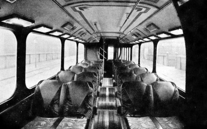
THE LOWER SALOON of a modern Glasgow tramway car, showing the roomy and luxurious interior. Loudspeakers are Fitted in the saloon, and the driver has in his cabin a microphone through which he can announce the next stopping place. Special precautions have been taken to counteract noise and vibration and to provide the maximum of comfort for driver and passengers.


 Total seating capacity is 65, there being 27 seats in the lower saloon and 38 in the upper. Both saloons are heated by tubular heaters. Eight roof ventilators in the upper saloon are arranged to operate whichever way the car is proceeding. To ensure ventilation in conditions such as a traffic jam in the centre of the city on a hot day, four fans connected in series and fitted in ducts are arranged to provide a maximum of one change of air every minute. Two types of lighting are fitted. That in the lower saloon is semi-
 DRIVER’S CAB of trolley bus. 1. Reverse. 2. Electric braking foot rest. 3. Battery-