

© Wonders of World Engineering 2014-


An ingenious engineering development to cope with railway, shipping and vehicular traffic
THE DOUBLE LIFT BRIDGE AT PORTLAND OREGON
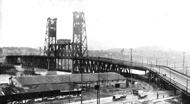
End view of bridge showing flared ends to the railway and the approach to the upper level.
ONE of the most perplexing situations in railway building is the necessity to cross a busy waterway at a low level, owing to the physical characteristics of the banks on either side. In order that no serious restriction may be imposed upon navigation, it is imperative that the bridge shall be provided with some means of opening so as to permit vessels to pass up and down easily. When this handicap is associated with a busy city, spreading over the opposite banks, the problem becomes aggravated, as the engineer is cramped for space in which to achieve his object.
Many ingenious methods have been elaborated to meet such conditions. There is the swing bridge, in which a span of the bridge is able to swing round in a semicircle upon a pivotal pier, thereby providing two channels -
Recently a new and ingenious development in connection with the last named method has been introduced. It is the patent of two American engineers, Waddell and Harrington, and it possesses many interesting features. The Oregon-
When the railway first entered the city it built a large steel bridge with a swing span, which it was concluded would meet all the requirements of navigation and yet at the same time would not hinder railway operations. But the trade of the port has increased amazingly during recent years, with the result that the swing span was constantly having to be opened and closed. On the yearly average this occurred 70 times a day -
Such frequent manipulations handicapped the railway traffic very seriously, so the company decided to build a new bridge across the waterway, 700 feet above the original swing bridge. This decision was seized as an opportunity to improve the vehicular and pedestrian traffic between the two banks, so a double deck bridge was adopted, the lower deck being for the railway, and the upper level for public use. But the question of protecting the navigation interests arose. The various methods of operating a moving span economically and expeditiously were investigated at length. In this case the problem was complicated by the top deck used by the public, which it was essential should be kept open as much as possible so that inconvenience to vehicular and pedestrian intercommunication might be reduced to the minimum. Obviously, both the swing and bascule systems had to be ruled out of court, because it was impossible to place the upper deck at such a level as to be beyond interruption at intervals. It was a peculiar problem which demanded a special solution. The railway engineers thereupon investigated the Waddell and Harrington invention, and finding that it met the situation very completely, it was adopted forthwith.
The river channel is crossed by three spans -

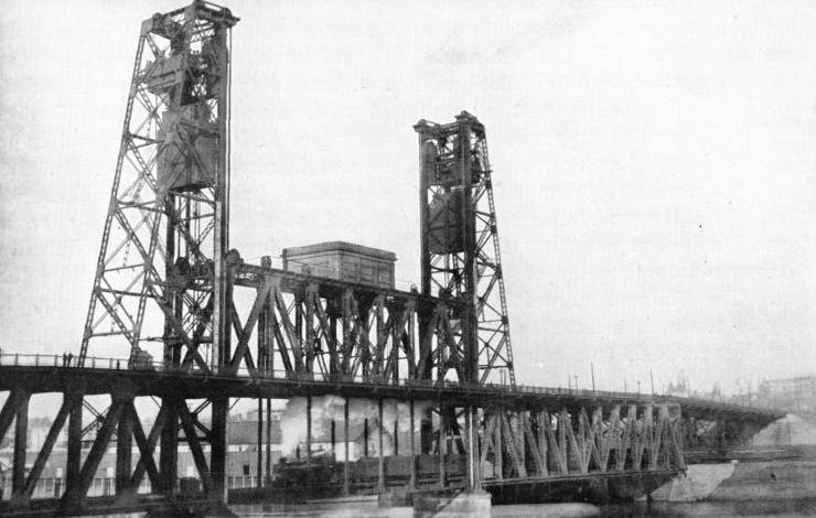
THE BRIDGE OPEN FOR VEHICULAR, PEDESTRIAN, AND TRAIN SERVICE
The trains run over the lower deck.
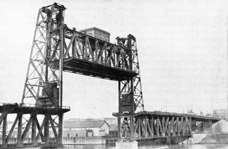
The moving span, which rises vertically between two towers by means of counterweights, is telescopic. That is to say, the moving span is so built that the lower deck may be raised independently of the upper deck. This is a distinct advantage, inasmuch as this vertical travel amounts to 46 feet. Accordingly, when the railway deck is raised until it touches the floor of the upper deck, a clearance of 72 feet above low water is secured. This is sufficient headroom for the greater proportion of the river traffic, so that there is no necessity to disturb the public highway. When, however, a large vessel with tall masts approaches, demanding a greater clearance, the bottom deck first is telescoped, and then, together with the higher level of the span, is lifted until the whole moving part comes to rest near the top of the towers, whereby a clearance of 165 feet at low water is given. By this provision all but the very largest craft coming to Portland are able to proceed through the bridge.
The independent movement of the bottom deck is accomplished by supporting the railway floor system and lateral truss on hanger posts from the upper movable span. Each hanger is connected to four cables, and is designed to move vertically inside the corresponding vertical post of the upper movable span. Both railway and public decks are counterbalanced with concrete weights. The lower moving section has eight of these counterweights, disposed four on each side, each section of four having an aggregate weight of 212 tons. The upper deck has two similar weights, each weighing 866 tons.
The river piers were sunk by the open caisson method. These were landed on cement gravel at a depth of 123 feet below low water. The six dredging wells were excavated to a depth of 10 feet below the cutting edge of the caisson, and the concrete was deposited under water by means of bottom dump buckets. In the completion of the sub-
The steel viaduct carrying the highway approach on either side was erected by means of a 30-
The building of the vertical lift span, and the movable railway deck, had to be carried out in such a manner that no interference was offered to the river traffic, and also in such a way as to be as independent as possible of the level of the water in the river. A clearance of 116 feet above low water was considered to be sufficient for the purpose. Four wooden cantilever brackets were put together on barges, and by means of the floating sheer-
In the erection of the two towers carrying the counterweights, as well as the sheaves, a gallows-

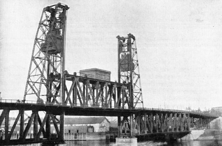
THE BRIDGE OPEN FOR VEHICULAR AND PEDESTRIAN TRAFFIC ONLY
The lower deck raised so as to telescope within the upper span.
The members of the lift span were handled by a traveller 96 feet in height. A construction tramway was laid on the upper deck of the east span and viaduct, over which a “creeper” car travelled. The steel was brought up on cars to the viaduct, and a derrick hoisted the sections therefrom on to the creeper car, which was then run out to the erecting point.
While the lift span was being built the casting of the concrete counterweights proceeded. These were prepared in their ultimate positions within the towers. The forms whereby these weights were moulded rested on boxes containing a layer of sand 18 inches in depth, and the moulds were placed 18 inches above the position they were to occupy ultimately. By this arrangement sufficient play for the stretch of the ropes, and to provide requisite ease in connecting the cables, was ensured. After the concrete had set, and directly the lift-
The lower or railway deck of the movable span was erected in sections on barges, a floor beam and two hangers first being riveted up, and then raised into position. The concrete counterweights for this deck were cast separately for each panel joint, and they were previously cast and supported on false-
By these ingenious arrangements the construction of the most difficult section of the bridge -
The machinery house for the operation of the moving sections is placed centrally on the deck above the highway level of the bridge. The mechanism is operated electrically. A large gauge is provided on either side of the bridge extending from the top of the piers to the point corresponding with the level of the telescoping railway deck, so that the navigator can determine the clearance available both when the lower deck and when the two spans are raised to the full limit of their respective travels. When the public level is lifted, the two descending counterweights block the thoroughfare on either side of the opening.
The total weight of the bridge is 8,585·8 tons, divided up as follows:—
West highway approach 687 tons
East highway approach 398·8 tons
Four 80-
East riveted span 2,230 tons
West riveted span 1,948 tons
Lift span with lifting deck 1,594 tons
Towers 799 tons
Tramway poles, balustrade, gas and water mains, etc. 342 tons
Machinery and motors 484 tons
While its total cost was £383,000.
The bridge was completed for railway traffic on July 23rd, 1912, while the public highway was finished a fortnight later. Since it was opened, the chief engineer of the railway informs me that the bridge has been working with perfect and entire satisfaction. The time occupied in raising both decks to the maximum clearance above low water -

THE BRIDGE OPEN FOR SHIPPING
The lower span is telescoped and the whole lifted so as to give a clearance of 165 feet on the navigable channel. The descending counterweights close the thoroughfare on the public level of the bridge.
[From Railway Wonders of the World by F. A. Tabot]
You can read more on “Building the Tower Bridge”, “Lifting Span and Swing Bridges”, and “Transporter Bridges” on this website.


