For more than four years thousands of engineers and labourers were engaged on the building of an enormous power scheme by which the waters of the River Shannon, in the Irish Free State, have been harnessed to drive massive turbines
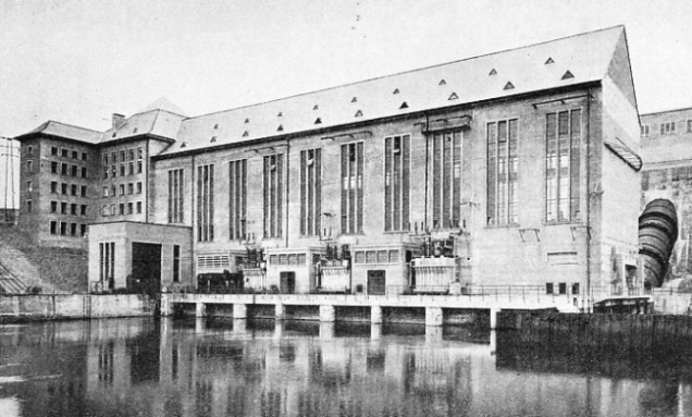
ARDNACRUSHA POWER HOUSE AND INTAKE WORKS at Ardnacrusha, near Limerick, Irish Free State. In the first stage of the scheme only three turbines were installed, with their connecting penstocks, but the openings in the intake building for the three additional penstocks may be seen. A fourth turbine has since been added. To the right are the spillway and the navigational locks, which open out of the headrace.
THE River Shannon, the principal river in Ireland and the longest (240 miles) in the British Isles, flows into the Atlantic on the west coast of the Irish Free State. From Limerick, about 170 miles from the source of the river, its estuary extends for seventy miles almost due west to the ocean. The Shannon drains a large area and flows through a series of three lakes known as Loughs Allen, Ree and Derg.
As early as 1915 the stretch of the river between Limerick and Lough Derg was surveyed with a view to a hydro-electric scheme. When the Irish Free State was established in 1922, the change in the economic life of the nation brought the suggestion to the fore. To establish herself as an economic unit, the Irish Free State needed plentiful supplies of electricity. If, however, that electricity were to be produced by coal, the Free State would be dependent upon external sources for the power that was to lead her to economic prosperity. When, therefore, a German firm of electrical engineers put forward, in 1924, proposals for the use of the Shannon to produce electricity, the matter was seriously considered.
Independent experts, engineers from Switzerland, Norway and Sweden, were asked to examine the proposals and on their findings the contract for the work was placed by the Government in August 1925.
The general plan of the scheme was rather unusual because of the nature of the countryside. In this district there are no such topographical features as the mountains of Galloway (see pages 175-185), where numbers of dams, aqueducts and tunnels diverted water from every direction to the five power stations. There is no rapid fall of water as from the Highland lochs, which are more than 1,000 feet above sea level. The fall of the Shannon between Lough Derg and Limerick, about twelve miles by river, is only about 100 feet. The country is low-lying and therefore it was not practicable to raise the level of any of the lakes to any degree and it would have been impossible to have dammed the river to form a reservoir.
For storage purposes the natural lakes provided the reservoirs. In a normal hydro-electric scheme a head of water is obtained by building a dam across a river and forming an artificial lake. Immediately below the dam the power house is generally situated so that a head of say 150 feet is available only as many yards away from the turbines.
In the Shannon Scheme, however, as it was impossible to dam the river and form a deep reservoir, it became necessary to divert the river into a canal. The canal forms a headrace seven and a half miles long to the intake situated immediately above the power station at Ardnacrusha. Ardnacrusha is about three miles above the town of Limerick. Water discharged from the turbines flows back into the River Shannon through a tailrace one and a half miles long. The line of the headrace and tailrace forms a short circuit for the waters of the Shannon, from a point about five miles below Lough Derg to Ardnacrusha.
THE INTAKE WORKS across the headrace at Ardnacrusha form a gravity dam 405 feet long, 23 ft 6-in wide and 24 feet high. Across the dam is a long machine-room which contains the machinery that operates the sluices and penstock valves. In the background is the structure which contains the sluice of the upper navigational lock.
The three lakes have a combined storage capacity of nearly 11,500 million cubic feet, and the fall of the Shannon has been harnessed to generate electricity in a power station with a capacity of 120,000 horse-power. If the weir at Parteen Villa (see map below) were to be raised, it would be possible to increase the storage capacity by more than half and to operate the plant with an additional capacity of 60,000 horsepower.
The Shannon Power Scheme was planned so that the additional capacity could be brought into operation with the minimum of difficulty. The headrace has been excavated to the full depth so that it will be able to deal with the maximum flow, and various embankments have been raised and river banks strengthened above the weir to prevent any possibility of flooding if and when it is decided to raise the weir and install additional plant. In the year ended March 1936, nearly 250 million units of electricity were generated by the turbines at Ardnacrusha power station. The scheme, though simple in construction, involved an enormous feat of engineering, for it included the building of numerous substations and the erecting of hundreds of miles of overhead transmission lines. For more than four years some 4,000 engineers and labourers were actively engaged mainly in the constructional work. More than a million cubic yards of rock had to be blasted, and nearly ten million cubic yards of earth were excavated.
Pocket of Earth Reinforced
Aerial ropeways, bucket dredgers, tower cranes and more than a hundred steam and electric locomotives were used while work was in progress. A temporary power station, with an output of 4,500 horse-power, was built to supply electricity for driving much of the machinery. Fleets of lorries, tractors and river craft were used for the transport of materials and machinery. Large camps were established for the accommodation of the workmen.
In March 1926 excavation began on the site of the power station at Ardnacrusha. The temporary power station had not then been built to supply power to drive the engineering machinery. The rock on this site was covered with from 40 to 50 feet of earth. Thus a considerable quantity of earth had to be removed, and this was used to form the banks of the headrace.
Two steam shovel excavators and a steam bucket excavator were used to excavate the enormous quantity of rock. The rock formed a foundation for the power station and the intake works except at one place where a pocket of earth occurred. This pocket, about 4,300 square feet in area, had to be strengthened and here also excavation was carried out to an additional depth of 10 feet. In the pit thus formed was laid a strongly reinforced concrete slab containing nearly 200 tons of steel.
The rock excavated was limestone, and much of this was used for concrete, road metal, railway ballast and other purposes. A large building at Ardnacrusha housed the crushing plant. The rock was loaded into trucks on rails, and the loaded trucks were hauled by a winch up an incline leading to the top floor of the stone-crushing building. From there the rock was emptied into the preliminary crusher, which had no difficulty in reducing blocks 26 cubic feet in content to pieces no larger than 183 cubic inches. Band conveyers then passed the materials to three graded crushers, which further reduced the rock to sizes suitable for various grades of stone or sand. Other conveyers led the material which had been crushed into two washing drums, one for the stone and one for the sand. Stones were carried through the drum by & screw which was perforated so that the water carried off loose earth through the perforations. The sand and smaller material were thoroughly cleaned by being continually shaken while water was being poured over them.
FINAL STAGES in the building of the intake works for the headrace at Parteen Villa. On the left is the passage for navigation. This opening is 33 feet wide. The three openings which admit water from the River Shannon into the headrace are each 82 ft 2-in wide. The openings are closed by steel gates with lattice girder stiffeners.
More perforated drums separated the sand into fine and coarse grades. The coarse material fell directly into the trucks on the railway and was carried away to be used for road metal and railway ballast. Sand was dumped into silos which stored material until it was required to be loaded into trucks or lorries for concrete making. A smaller but similar plant was built at another point in the Shannon Scheme.
The excavation of the seven and a half miles of the headrace involved the removal of more than 150 million cubic feet of earth and more than 10,000,000 cubic feet of rock. Five multiple bucket excavators, operated by electricity from the temporary power station at Ardnacrusha, were used to excavate the earth. The headrace was excavated to a depth of 57 ft 5-in. For the greater part of its length the headrace was formed partly in cuttings and partly between embankments. The slope of the side of the trench was formed at an angle of forty-five degrees, and in one place the embankments reached to a height of 59 ft 6-in.
Two main considerations affected the size and design of the headrace. First, it was decided to make the headrace large enough at the outset to hold the water that would be necessary for the full development of the Shannon Scheme. Secondly, it had been decided that the headrace should be used also for navigation. The headrace has been so built that the maximum speed of the current will not exceed five feet a second. When the scheme is working to full capacity 17,658 cubic feet of water will flow through the headrace every second, and the width of the water at the surface will be nearly 300 feet. The centre of the headrace was additionally excavated for a width of 102 ft 4-in, so that in this section the total depth of the water will be 36 ft 9-in.
Track-Moving Machine
The bucket excavators ran on special tracks along the line of the headrace. The buckets of an excavator formed a continuous chain so that the excavator resembled the bucket tower of a dredger. The excavated material was hauled up by the buckets and emptied into trucks which ran on rails that were laid under the excavator. The width of the headrace made it necessary to shift the rail tracks sideways as the excavation proceeded from the centre to the outside. Normally this would be a long and tedious job carried out by a gang with levers. A special track-moving machine, however, was used for this purpose.
Where rock was encountered, blasting operations came into force. Boreholes to take the explosives were drilled by drop-hammer machines driven by compressed air. These machines closely resemble the boring appliances often used for drilling artesian wells. From the sheer-legs the heavy chisel drops and pierces the rock. Three boreholes of 8-in diameter were found to be sufficient to blast more than 35,000 cubic feet of rock. The rock, when blasted, was loaded into trucks by shovel excavators, some of which travelled on rails. Others were mounted on crawlers so that they could move over the ground without the necessity of rails being laid.
For building the embankments special, transporters were used, machines similar to those used for obtaining brown coal in Germany. A transporter of this type on the Shannon work was probably the first to be used for raising embankments. The first operation carried out by this machine in raising the embankments is, paradoxically, to excavate a trench about 8 feet deep. Trains bring earth which is discharged into the trench. Bucket chains on the transporter then scoop up the earth from the trench and empty it into a hopper.
THE RIVER SHANNON is partly diverted at Parteen Villa, below Lough Derg, into a headrace seven and a half miles long, to Ardnacrusha. Here the power house is situated and the tailrace leads the water back to the main stream of the Shannon a short
distance above Limerick.
The hopper drops the earth on to a conveyer belt which is supported from the transporter boom. The earth is carried by this conveyer to a second conveyer supported in such a way that it can move up and down the boom. This makes it possible for the earth to be deposited over a large area. This arrangement had many advantages, as it was not necessary to move the rails on which the transporter ran except in places where the embankment was wider than usual. The height from which the earth was dropped also had the effect of ramming it home more securely than if it had merely been dumped from a wagon.
Where the slopes of the headrace cuttings and embankments were not sufficiently watertight a layer of clay about 2 feet thick was superimposed. Broken stones were laid in the bed of the headrace and on the slopes to overcome erosion by water. On the water-line concrete slopes were laid to provide protection against the action of waves which might be caused by wind, by a sudden stoppage of the turbines or by the passing up or down of a vessel. To effect this part of the work, rails were laid at the bottom of the channel. Trainloads of materials, stones or clay were emptied into steel skips alongside the track. The skips were lifted by 2-tons electric swivel cranes and tipped where desired.
The line of the headrace between Ardnacrusha and the intake works at Parteen Villa is crossed by a number of roads and streams. Three bridges of reinforced concrete were thrown across the headrace to carry the roads. The most important of these bridges has three spans, of which the centre span is formed by a girder 115 ft 6-in long. A headway of 11 ft 6-in was allowed to enable navigation to pass under the bridge.
Some of the streams could be passed beneath the headrace by ordinary culverts which presented no difficulty. In certain instances, however, siphons had to be built under the headrace. To prevent percolation of water from the headrace into a culvert, layers of clay covered with stones were applied to the bottom of the headrace over the line of the culvert.
Water is diverted into the, headrace by a weir across the River Shannon at Parteen Villa. The weir and the intake works form an almost continuous structure, meeting at an angle of about 135 degrees.
Cable cranes, or telphers, were erected to facilitate the building of the weir and intake works. The cable cranes extended from a central tower between the intake and the weir. The cables spanning the river and the headrace were fixed at the opposite ends to towers which could be moved in the direction required.
The intake structure consists of three piers and two abutments. Water is admitted into the headrace through three openings, each of which is 82 ft 2-in wide. The intake openings are closed by steel gates fitted with lattice girder stiffeners having rollers which run on vertical steel guides fixed in the piers.
The gates are supported by chains and operated from machine-rooms built on a steel gangway which spans the piers and abutments. The piers are built of reinforced concrete with foundations carried down into the bedrock. To allow ships to pass into the headrace a further opening 33 feet wide has been provided.
The weir is a reinforced concrete structure founded on rock and is designed to impound 29 ft 6-in of water. There are six openings, two of them being 59 ft 6-in wide and the remainder 32 ft 9-in wide. The hoisting machinery for the gates is in a roofed gangway over the weir itself.
MULTIPLE BUCKET EXCAVATOR AT WORK on the excavation of the headrace. Five similar machines, operated by electricity from a temporary power station at Ardnacrusha, were used to remove more than 150 million cubic feet of earth in the headrace channel, which was excavated to a depth of 57 ft 5-in. The cutting buckets run on the underside of the boom.
Cofferdams were formed so that the foundations of the piers could be excavated. Rock drilling was carried out by compressed-air
hammers, and five pumps were used to keep the cofferdam dry enough for excavation to be undertaken. The weir was built in three sections so as not to interfere with the normal flow of the Shannon. The first section was that on the northern bank of the river nearest the intake works. The central section was built last, and before it was finished water was passed into the headrace through the intake works.
Above the Ardnacrusha station the headrace is widened out into a forebay, which reduces the velocity of the water. Immediately above the power station the headrace is dammed by the intake building. This is in effect a gravity dam 405 feet long, 23 ft 6-in wide and 24 feet high. Foundations were carried down to the natural rock and the entire site was grouted to a depth of 49 feet to prevent the danger of water percolating from the headrace through fissures in the strata.
Openings in the intake structure admit water to the penstocks,. which have a diameter of 19 ft 8-in. The full development of the scheme allows for six penstocks. Across the inlets are cast-iron grilles known as trash racks, which prevent solid matter from entering the penstocks. The penstocks, which connect with the spiral casings of the turbines in the power house, are prominent features of this part of the Shannon Scheme. Built of high-tensile ‘steel, they are 131 feet long and are laid on a slope of 31 degrees. Flow through the penstocks is controlled by gates operated from the gatehouse, which extends along the whole length of the dam.
At the southern end of the dam is a high structure which has the appearance of a triumphal portal, with a lintel instead of an arch. This is the gatehouse for the navigational locks opening out of the headrace. Two locks lower boats from the headrace a distance of 100 feet to a navigational channel which connects with the tailrace.
The lower lock is filled by emptying the upper lock into it. The lower lock empties, not into the navigational channel, but through a special conduit into the tailrace. The locks of Ardnacrusha are designed to accommodate vessels of up to 150 tons.
Between the locks and the penstocks is a spillway channel which carries water that may be released from the headrace by an emergency valve operated from the gatehouse. Thus when one of the turbines is shut down and its penstock closed, the emergency valve is opened to compensate for the arrest in the flow of water which would otherwise cause a turbulence in the headrace and a loss of water in the tailrace - conditions dangerous to navigation.
The power house is a splendid example of Teutonic architecture. The intake buildings, too, have such an external appearance that the mere sight of them is enough to suggest that they are the work of German engineers. No attempt has been made to give these buildings any unnecessary or superfluous decoration. They are, in Ireland at any rate, pre-eminent examples of the impressiveness of functional architecture.
WEIR AND INTAKE WORKS at Parteen Villa form an almost continuous structure across the river and the headrace, meeting at an angle of about 135 degrees. During construction cable cranes, or telphers, were erected to span the river and the headrace from a central tower between between the intake and the weir. The cables spanning the river and the headrace were fixed at the opposite ends to towers which could be moved as required.
The main generator hall is more than 200 feet long and 61 feet wide. Three turbines were installed to complete the first part of the Shannon Scheme. When the development of the scheme is complete there will be six turbines. Each of the turbines so far installed has a maximum output of 38,600 horsepower, with a water consumption of 3,612 cubic feet a second. The turbines are of the Francis vertical-shaft type and are coupled to generators rated at 30,000 kVA. The spiral casings of these turbines are among the largest that have been built. They are so large that it was impossible to deliver them complete to the site. The steel plates of the casings had to be riveted together in position on the site. The spiral casings are completely embedded in concrete and have an external diameter of about 39 feet.
Each turbine is provided with two servomotors, which are driven by oil under pressure and are situated immediately next to the turbines. Electrically driven gear pumps supply the servomotors with oil under pressure. The enormous weight of this machinery had to be allowed for when building the power house. The revolving parts of each turbine weigh 227 tons. The stator weighs about 200 tons and hydraulic loads of 275 tons had to be allowed for. This weight is carried mainly by reinforced concrete piles.
ARDNACRUSHNA POWER STATION and the intake works behind it are imposing examples of the impressiveness of functional architecture. From the power house current is supplied to all parts of the Irish Free State through 110 kV, 38 kV and 10 kV overhead transmission systems.
The turbine and generator bearings are lubricated by independent systems. Oil pumps are used, driven through gears from the turbine shaft. Emergency water cooling apparatus will keep the bearing cool for two hours after the oil circulation fails, if that should happen for any reason. The generator bearings are lubricated by a circulating oil system. From a tank situated at the lowest point of the circulating system an electric pump forces oil into a tank which is on a level with the crane runway. From this tank the oil flows by gravity through the bearings. The tanks are sufficiently large to maintain the flow of oil for three hours should the pump cease to function. In addition, the upper and lower tanks of all generators are interconnected.
An ingenious system of visual and audible signals indicates in the control room of the power house failure at any point in the lubricating system. Similar devices automatically switch off the generators in the event of a short circuit or any other fault. No sooner is a machine stopped because of a fault than a carbon dioxide fire-extinguishing apparatus is put into operation. Any fire which may be, started can be extinguished in four seconds by this method.
Network of Transmission Lines
Current from the generators is stepped up to 110 kV and 38 kV by three 30,000-kVA and two 8,000-kVA transformers respectively. The electricity is distributed throughout the Irish Free State through three transmission systems. The cities of Dublin and Cork have substations which are fed at a pressure of 110 kV from Ardnacrusha. From these two substations and from Ardnacrusha itself extends a 38-kV network over the country. From the 38-kV substations current fed at 10 kV to local substations which step it down to 220 volts for local distribution in the country.
One of the major parts of the Shannon Scheme, therefore, was the building up of the intricate network of overhead transmission lines. The total length of the conductors amounts to 2,150 miles, the greater length of which is carried on steel lattice masts. To prevent corrosion in the damp climate of Ireland all exposed parts of the pylons are treated with anti-corrosive paint. The normal span between the pylons is 273 yards for the 110-kV lines. In certain places the span had to be increased to a maximum of 525 yards between pylons 164 feet high.
As in the Galloway Scheme provision had to be made to allow fish to pass the weir. The fish ladder at Parteen Villa is one of the largest in the world. It has a length of more than 600 feet and consists of a series of steps and pools.
The Shannon Power Scheme is operated by the Electricity Supply Board, whose headquarters are at Dublin. This body is the main authority for the supply of electricity in the Irish Free State, and it is continually extending its scope. Every year the generating plant is extended, the areas supplied grow larger and the transmission network increases. The Shannon Scheme is capable of being developed to full capacity when circumstances permit.
BLACKWATER BRIDGE was built to carry a road across the headrace. The bridge has three spans of reinforced concrete. The distance between abutments is 249 feet and the centre span is 111 ft 6-in wide.
Additional illustrations from the photogravure supplement can be seen here.


 For building the embankments special, transporters were used, machines similar to those used for obtaining brown coal in Germany. A transporter of this type on the Shannon work was probably the first to be used for raising embankments. The first operation carried out by this machine in raising the embankments is, paradoxically, to excavate a trench about 8 feet deep. Trains bring earth which is discharged into the trench. Bucket chains on the transporter then scoop up the earth from the trench and empty it into a hopper.