The automatic control either of mechanical operations such as the starting of ships or aircraft, or of plant such as a boiler installation or a battery of air compressors, can be carried out by servomotors, whose functions duplicate those of human controllers but eliminate the human element
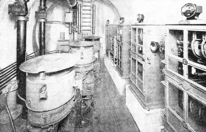
AUTOMATIC PUMPING STATION used for pumping the water from the drainage sump beneath the Mersey Tunnel. Situated beneath the river, the pumps are automatically started or stopped by the electrical control system — shown in part on the right — according to the variations in the load.
IN the control of machinery the human element can be virtually eliminated. The functions of the man who controls the forces of a mighty engine can be carried out by automatic mechanical means. It might be said that his physiology is reproduced by delicate machinery.
The function of the brain is carried out by a master controller which receives impressions and transmits them by relay circuits, corresponding to the nerves, to what are known as servomotors. These perform the mechanical functions of human muscles. In the same way as muscles derive their power from blood pumped by the heart, servomotors operate with a fluid medium supplied from a central pumping system.
An excellent example of automatic control superseding human control is provided by an ordinary boiler installation. The fireman has several duties to perform and various things to watch. As the demand for steam increases or falls off he has to shovel on more or less coal. He has to operate the flue dampers accordingly, to start, stop or vary the speed of the feed pumps to maintain the water level in the boiler. Nowadays a complete boiler installation can be run almost entirely by automatic control.
Variations in the demand for steam cause corresponding fluctuations in the steam range, or main, and in the steam pressure of the boiler. The capacity of the boiler to maintain its pressure depends mainly on the quantity of fuel burnt, on the draught and on the air supply. Thus these are the main functions to be controlled. Automatic control systems take as their initial governing element the volume, temperature or pressure of steam, water, air or gas, or a combination of two or more of these. In boiler control, steam pressure is the main determining factor from which the whole system takes its lead.
A small steam pipe with a diameter of about ½ in. connects the steam main to a master controller. The function of this is to send out a pneumatic, or hydraulic control pressure, whose variations are amplifications of the small pressure variations which occur in the steam main. Such a controller is sensitive to fractions of one pound per square inch. These variations are measured by metal bellows, whose expansion or contraction is transmitted to a small double-seated pilot valve through the medium of a steel pin pressing on a balanced bar pivoting on a knife edge.
A continual oil or air pressure is supplied to the pilot valve. The oil pressure circuit, through ¼-in. pipes, then passes through a switching valve which gives two positions for operating — either “automatic” or “manual”. From here the pressure passes to one or more relays. The control pressure sent out by the relays depends on the pressure received from the pilot valve, and also on the amount of pressure applied by a hand regulating wheel to a spring contained in the relay.
The relays are connected by small oil pipes to various servomotors, which operate the mechanisms that affect the amount of fuel being fed to the boiler, the induced draught fan and the forced draught fail. The oil pressure supplied to the servos may be anything between 55 lb. and 100 lb. per sq. in., and comes from the same pumps as feed the master controller pilot valve, although the supply for this passes through a reducing valve which maintains the pressure constant at 50 lb. per sq. In.
A servomotor of normal dimensions has a cylinder of 2½ in. or 5 in. bore, with a stroke of 10 in.; it may be worked either by compressed air or by hydraulic pressure. The servomotor may receive a control pressure from the master controller, or from any other type of sender regulator or relay, and has a means of balancing the pressure by a spring. The variations in this control pressure, which occur when operating conditions change, are used for operating only a small pilot valve, which in turn controls the power supply medium to the servo cylinder. This movement continues until a compensator, an inclined bar fixed to the servo frame, has decreased or increased the spring pressure to balance the control pressure. There is a definite relationship between the control pressure variation and the piston movement, which can be altered by setting the compensator bar.
The pilot valve admits the power medium to either side of the piston of the double-acting power cylinder, at the same time opening the other side to the atmosphere. The length of the stroke bears a direct relation to this variation. The ball crossheads of the piston rods are generally connected by rods to levers on the flue dampers, to fan vane regulators, or to rheostats controlling the speed of electric motors, such as the mechanical stoker motor.
In draught regulators, any variation in the draught or air flow conditions which the regulator has to maintain causes a movement of floats, or diaphragms, which are partly submerged in oil. Such movement is transmitted to a pilot valve which admits the power medium to either side of the servo piston, so that the position of the power piston depends on the variation in draught or air flow.
One of the most outstanding instances of servomotor control is provided by the steering gear equipment of such a ship as the Queen Mary. The rudder of this ship is about 500 square feet in area, and the pressure exerted on its surface, when placed hard over, with the ship going at full speed, amounts to several hundreds of tons. This pressure has to be held, and the rudder movements controlled by hydraulic rams operating on either side of the rudder post arms. Yet a liner of some 80,000 tons, travelling at about 31 knots, can be turned to either side by means of a light pressure on a single spoke of a small steering wheel no larger than that of a motor car.
The method of operation is briefly as follows. Oil pressure is supplied to four hydraulic cylinders — arranged in pairs on either side of the rudder stock — by means of three high-pressure variable delivery pumps, each driven by an electric motor of 250 horse-power. One of these, however, is capable of moving the rudder hard over with the ship steaming at full speed. The fluid delivery from the pumps is controlled by a system of control and “hunting” gear, and as the effort required to perform the function of varying the pump delivery would be too high for normal manual control, a complete servomotor gear is provided.
THE CONTROL ROOM in the New Homestead Mill of the Carnegie-Illinois Steel Corporation U.S.A. Rows and rows of circuit breakers and other electrical equipment form part of the intricate mechanism by which impulses are transmitted into action and the machinery of the mill is controlled.
This servo gear is of the electro-hydraulic type and has two smaller variable delivery pumps and motors of about 4 brake horse-power, which supply fluid to duplicated hydraulic cylinders which operate the main steering gear control mechanism. The servo gear is in turn controlled from the ship’s bridge by duplicated hydraulic telemotors. The steering wheel of the telemotor is operated by the helmsman and has nothing more to do than to operate a small pump which controls the supply of oil to the main pump control system.
This small pump control is also connected to a gyropilot which can automatically control the whole steering equipment for an indefinite period without human hands touching it.
Movement of the small steering wheel of the hydraulic telemotor transmitter on the ship’s bridge causes a corresponding movement of the telemotor receiver piston. This movement puts more or less stroke on the servo pump which delivers oil to the servo hydraulic cylinder, the piston rod of which operates — through a floating lever — the control lever of the main variable delivery pumps. This pump delivers oil under considerable pressure to two of the four main hydraulic ram cylinders. The consequent movement of the tiller crosshead is transmitted by the hunting gear back to the floating lever, and thus to the main pump control lever, bringing the pump to “no stroke” position, and stopping the steering gear when the rudder reaches an angle corresponding to the position of the steering wheel.
Another application of automatic control is in ship stabilizing devices. One method of preventing the rolling of ships is by the use of stabilizing tanks. Water tanks are located inside the skin of the ship at either side and connected with each other at the bottom by an inside transverse channel, the tops of the tanks being connected by an air duct.
Ship Stabilizing Equipment
The mass of water contained in these tanks forms a controllable ballast which can be diverted to one side or the other to counteract the rolling caused by a heavy sea and to create a damping effect. Here again a gyroscope forms the master controller. The movement of the ship to one side or the other, in relation to the fixed gyroscope, causes electrical contacts to be made which energize one or the other of two electromagnet solenoids.
The solenoids move an oil valve which admits oil under pressure to one side or the other of two hydraulic cylinders, which control the direction of flow of slightly compressed air. This is discharged by a blower into, say, the starboard side tank, and exhausts the air from the port tank, thereby producing more rapid displacement of the ballast water than would be obtained by relying on a gravity flow.
SERVOMOTOR CONTROL for the steering gear of the Queen Mary. The layout of the installation is shown in the diagram at the top of the page. On either side of the head of the rudder post (RP in the diagram above) are the main hydraulic rams (MHR). These actuate the rudder and are operated by three main pumps which, with their motors, appear in the centre of the equipment. The servo gear is on the extreme right.
Where the demand for compressed air is continually varying, considerable economies can be effected by the automatic regulation of the compressors, operated by means of a pressure gauge. Take, for example, a battery of six 40 horse-power air compressors with adjustable intervals of from five to fifteen minutes in the period between the starting of successive compressors, and of from one to ten minutes in the stopping, to give adjustment to correspond with the rate of change between minimum and maximum. These conditions have been met by the design of a special form of master controller.
A pressure regulator, comprising two Bourdon pressure gauges with adjustable electrical contacts and two control circuit relays, is arranged to govern a pilot motor which drives a master controller through high-ratio reduction gear. Electrically operated contactors, connected between the pressure regulator relays and the pilot motor, are arranged to make and break the pilot motor circuit in the forward and in the reverse directions of rotation.
The apparatus is so arranged that if the air pressure remains below a predetermined value, adjustable between 25 lb. and 28 lb. per sq. in., additional motors will be started up in sequence, and at adjustable intervals of time, as regulated by the movement of the master controller. When the air pressure rises above the predetermined value the movement of the master controller is stopped, and the number of motors running remains unaltered until the air pressure either falls again below the predetermined limit or rises above, say, 30 lb. per sq. in. This figure also is adjustable, and it is arranged that, if this pressure limit is exceeded, the motor last started in sequence is immediately stopped, and the master controller is moved in the direction to stop the other motors in sequence and at the predetermined rate.
The motor-driven master controller is housed in a steel pillar type floor case, with inspection doors which are interlocked with the main isolating switch so that the doors cannot be opened unless the isolator switch is in the “off” position. The sequence limit switches are actuated from a moving nut mechanism driven along by a square-threaded leading screw. Ultimate limit switches are provided to prevent accidental overtravel at either extremity. An adjustable automatic timing device causes the resistances to be cut out correctly, step by step, until full speed is reached. A solenoid-operated pilot valve, working in conjunction with the unloading valves on the air compressors, enables them to remain unloaded during the starting periods; this limits the starting peaks and reduces wear and tear.
Directional Control
In many instances pump control is simply effected by control gear operated by the rise and fall of a float on the fluid being pumped, when the only functions required are the starting or stopping of the motor in relation to the level of the fluid supply.
Possibly the most ingenious form of automatic control is that of an aeroplane by means of the gyropilot. The control of the direction of a ship at sea has to be effected in only a horizontal plane to port or to starboard — but an aeroplane has to move in three directional planes. A turn right or left is effected by the rudder, movement upwards or downwards, by the horizontal rudder, or elevator. A lateral movement, when banking, is secured by movement of the ailerons at the wing tips, and is generally combined with the turning movement of the vertical rudder.
The gyropilot is based on the “rigidity” of the spinning wheel of a gyroscope. The application of this principle of the gyroscope to control the movements of aircraft is effected by a combination of gyroscopes, relays and servomotor units which act together.
One gyroscope of the aircraft gyropilot — -for its directional control — is of the “free” type — that is, it is free to move round three axes. This gyroscope has a compass card attached to it and rotates with its axis horizontal. Another free gyro — for the control of bank and climb — rotates with its axis in a vertical position, and must absolutely maintain its position. When this gyroscope diverges from its upright position, four light pendulous vanes on the underside of the gyro housing remain vertical, due to gravity. These vanes control the volume of air which is being exhausted from four air ports, each of which is half covered by its pendulous vane when the gyro axis is vertical. If the gyro tilts out of the vertical a greater volume of air is exhausted from one port. This causes the gyro to precess back to the vertical position. Control for automatic flying is effected through a system of
“air pick-offs”. There are three sets of air pick-offs — two giving lateral and longitudinal control and one for the gyroscope which gives directional control. The automatic functions are carried out in the same way whether they operate the ailerons, the rudder or the elevator of the plane.
Each air pick-up comprises two ports diametrically opposite to each other on either side of the gyro periphery. When the attitude of the aircraft is normal about all axes air from air relays flows equally through these ports, being drawn into the gyro box, or case, due to the depression therein of about 4 in. of mercury. For aileron control, when the aircraft deviates from level flight, the air pick-offs, which form an integral part of the plane and are independent of the gyro itself, take up a new position in relation to the gyro, which maintains its original position.
LAYOUT OF THE SPERRY GYROPILOT FOR AIRCRAFT.
(AF) Air filters; (BPV) By-pass valve; (SCV) Spped control valve; (SV) Safety valve.
Directional arrows show aileron controls in operation.
As the plane banks to one side or the other, taking the air pick-off mechanism with it, the partial rotary movement of the two air ports in relation to the fixed position of a plate on the gyro mechanism causes one or other of the ports to be uncovered. More air is sucked through the open port than through the closed one. This causes deflection of a diaphragm in the air relay, because of the difference in pressure on its two sides. This diaphragm is connected by a rod to a balanced oil valve, which controls the flow of oil to and from the servo cylinders.
The movement of the diaphragm transmits a corresponding movement to the oil valve, through which oil under pressure, derived from an engine-driven oil pump, is delivered to the servo cylinder, applying pressure on the piston in this cylinder in one direction or the other as required. The servo piston rod is connected by wire cables, which transmit the desired function to the levers on the ailerons.
In controlling an aeroplane, it is necessary not only to apply control to bring the plane back to level when it has been disturbed, but also to begin to remove the applied control as the plane is returning to level, so that the plane control surface—whether aileron, rudder or elevator—will be in neutral position when the disturbance has been fully corrected. A further requirement is that the amount of control which is applied shall be in proportion to the displacement of the aircraft concerned. All this is necessary to manual and automatic control. With automatic control it is handled by the follow-up mechanism, which is somewhat similar to the hunting gear in a ship’s steering equipment. The air pick-offs are not fixed rigidly to the gyro box and to the plane, but can, instead, be moved in relation to them by the follow-up mechanism. A cable is connected to the servo piston rod, and is run to a follow-up pulley on the gyro box. The pulley controls a gear which is connected to a corresponding gear on the air pickoffs, which are commonly connected.
When the servo piston moves in one direction the piston rod pulls the follow.-up cable attached to it, and this in turn pulls back the air pick-off until the two air ports reach the neutral position, both of them being half open. In this position the depression on either side of the diaphragm in the air relay is equalized, and the centralizing springs of the balanced oil valve bring it into its neutral position, so that the servo piston movement away from neutral is stopped. As the aircraft continues towards the level position the air pick-offs, which have been driven ahead of the gyro box, pass beyond the neutral point and begin to cause servo movement in the opposite direction. This is not opposite control, but is the removal of the control originally applied.
Closing Watertight Doors
The mechanism and its ratios are so arranged that the correct amount of control will be applied, and also removed at the proper rate as the aircraft returns to level. The pick-off ports may be controlled also by the human pilot, so that he is able to manoeuvre his machine about all axes without disengaging the automatic control.
The safety of a ship at sea largely depends in an emergency on the speed with which the watertight bulkhead doors can be closed. This important operation is now carried out by the use of servomotors, automatically controlled from a master control valve on the ship’s bridge. The bridge control valve is connected by small-diameter pipes containing the power fluid medium —water at about 700 lb. Pressure — to each of the watertight door stations. The hydraulic pressure is admitted to one end or the other of a hydraulic servomotor cylinder, which operates a toothed rack-and-pinion gear on the back of each door. An electric bell signal of five or six seconds duration is given at each door ; after this warning all doors connected to the system can be closed in about twenty seconds. As soon as the doors begin to move, mechanically operated bells on the door mechanism ring until the doors are closed. Immediately a door has reached its closed position a glass disk — corresponding to that door — is illuminated on the electrical indicator plan of the ship, placed on the bridge.
The servomotor principle is used also on thousands of motor cars, heavy commercial vehicles and buses for relieving the human effort of applying brakes. The vacuum servo system uses the vacuum created by the suction of the induction pipe.
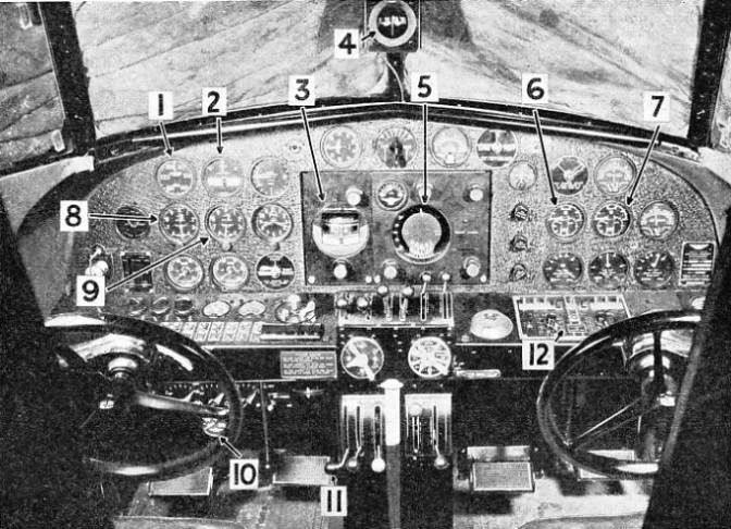
CONTROL PANEL OF AN AEROPLANE fitted with Sperry gyroscopic instruments and control equipment. 1. Air speed indicator. 2. Turn and bank indicator. 3. Directional gyro. 4. Magnetic compass. 5. Horizon unit. 6 and 7. Combined oil pressure, fuel pressure and oil temperature gauges for port and starboard engines respectively. 8 and 9. Altimeters. 10. Oil pressure gauge for gyropilot. 11. Main “off” and “on” levers of gyropilot. 12. Radio control panels.


 The method of operation is briefly as follows. Oil pressure is supplied to four hydraulic cylinders — arranged in pairs on either side of the rudder stock — by means of three high-