


© Wonders of World Engineering 2014-


The disposal of the refuse of a large industrial town is a problem that has been treated in a variety of ways. In many place rubbish is now burnt in specially designed furnaces and used to generate electrical power
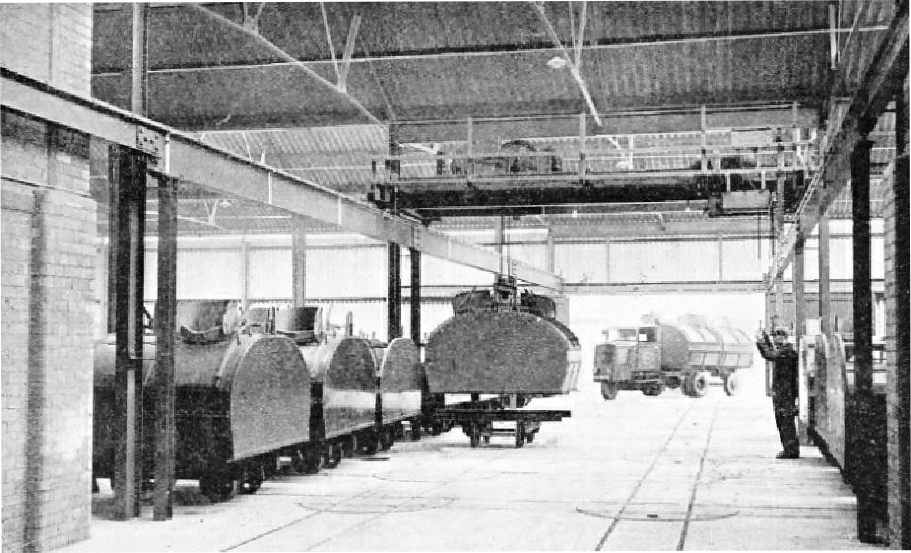
THE INCOMING REFUSE is brought to the destructor in special enclosed containers with a capacity of 3¾ cubic yards. Two or sometimes three containers are mounted on one lorry. They are lifted by a crane on to bogies to be parked by a system of rails and turntables. When the refuse is required for incineration, the containers are taken by a telpher for discharge into the destructor.
.
OLD methods of dealing with enormous quantities of refuse, such as dumping the material on waste ground and allowing it to smoulder or rot, are entirely out of place in a modern civilized community. The ordinary rubbish tip or dump shows no advance than that made uncounted centuries ago, when some progressive palaeolithic householder invented the kitchen midden and shot all his rubbish on to one pile instead of strewing it in insanitary profusion round the mouth of his domestic cave.
Rubbish should be destroyed, not dumped. We have not yet succeeded, however, in procuring complete destruction of rubbish; but modern engineering science has secured the partial destruction of refuse by fire. There are also methods whereby the matter is first screened and has certain of its ingredients extracted before it is passed into the great destructor furnaces which reduce it to an innocuous mass of ash and clinker. Other adjuncts have been adopted in various places during recent years, such as the installation of boilers in conjunction with the furnaces for the supply of steam to adjacent power plant. Yet even to this day some large cities retain the dump system to a great extent. Huge rubbish heaps, over 90 feet in height, cover some 150 acres of ground at a dump outside London, and these unpleasant ornaments to London’s outskirts are added to from day to day.
The modern refuse destructor, designed to eliminate such anachronisms as these, is an elaborate and fascinating installation. Types of destructor vary considerably. Different places produce different types of refuse. A typical large British town produces a high percentage of cinder waste and this increases in industrial areas adjacent to coalfields. An American town, where central heating is general, produces less cinder waste, and so does a German town in which the houses are heated by high stoves burning briquettes. The West End of London, with its huge hotels and department stores, produces an undue quantity of paper waste — the remains of cardboard boxes and wrappings. An Eastern city will be notable for the immense quantities of vegetable garbage it produces.
In the city of Birmingham, a typical large British industrial city, cinders form a little less than 20 per cent of the average type of refuse brought in. By far the largest proportion is that of fine dust, reminding us that the old-

CENTRAL CONTROL PLATFORM of an inclined rotary refuse destructor. The controls can be seen at the left of the photograph, near the ignition grate in which the refuse is fired. On an illuminated instrument panel are recorded the carbon dioxide content of the waste gases and furnace temperatures at the combustion grate and at the flue leading to the boiler.
POWER FROM RUBBISH. This condensing turbo-
An interesting method of dealing with the innumerable “tins” is that adopted at Huddersfield. The designers of the refuse destructor plant there have installed a magnetic separator which draws the broken cans out of the raw garbage before it is fed to the furnaces. The cans are placed in a hydraulic press which squeezes them into compact bundles. These are then sold at current market rates.
Apart from variations in the composition of refuse due to locality, there are also, in temperate regions at any rate, variations due to season. There are more cinders in winter than in summer. The destructors in such situations have therefore to be “flexible” in operation.
The designer of the modern destructor has certain essential requirements to fulfil. The calorific value of refuse is low, and cannot therefore be treated in the same way as coal, coke or other orthodox fuel. All solid fuels, it is true, give better results if they are fed continuously to the furnace, as by a mechanical stoker. With the refuse destructor, this is imperative if the apparatus is to serve its purpose with any degree of efficiency. Charging must be as nearly continuous as possible, and the continuity of discharging the clinker and unburnable remains must be maintained in harmony. Because of the moist nature of the fuel, and its tendency to slow down combustion, it is advisable for it to pass through some form of preheater which dries it before it passes into the incinerator, proper.
Totally Enclosed
Especially where the furnaces are in conjunction with boilers for the generation of steam, care must be taken to ensure an even rate of combustion and a consequently even temperature of the furnace gases. Where combustion is thoroughly efficient, much of the dust contained in the refuse will be burnt or fused with the clinker, but a proportion of it will eventually mix with the gases produced by combustion. Means must be provided for removing this before it passes into the smokestack, and also for ensuring that it has as low a carbon content as possible.
In foreign towns where the refuse is particularly low in calorific value, as happens in Eastern localities, it is sometimes necessary to mix it with certain solid or liquid fuels to ensure complete combustion. This is not necessary, on the other hand, in a typical large British town. At Birmingham, for instance, where all the destructor plants have been harnessed for the generation of power, no fuel is used apart from ordinary refuse.
Air for combustion purposes passes to the furnace through specially controlled inlets. Care must be taken to prevent infiltration of air apart from this regulated flow, as unregulated air destroys the efficiency of the incinerator. The fuel which passes into a destructor furnace is invariably offensive in character, and special precautions need to be taken to prevent it from becoming a nuisance.

IGNITION GRATE AND ROTARY KILN after having been in operation for eighteen months. The brick lining of the kiln is comparatively free from clinker, due to the cascading action of the material in the kiln.
As far as carriage is concerned, there is the modern closed refuse wagon, as opposed to the old-
The layout of one of these destructor plants is best understood from a description of the several stages through which the refuse passes. First of all the garbage is charged, almost continuously, though a vertical chute, into a pre-
The ignition grate itself is situated at a lower level than the pre-
Exposure to Hot Gases
Air for combustion in the ignition grate is fed to it at low pressure through a series of air chambers situated underneath. At the base of the air chambers, in their turn, is a series of hoppers for the collection of dust which passes through the bars of the rocking grate. Each air chamber is equipped with a damper, so that the flow of air to any part of the grate can be regulated according to local requirements.
From the ignition grate the partly burnt refuse passes automatically into a rotary kiln. This is a huge revolving cylinder on an inclined axis. As it turns, every part of the charred mass of refuse inside is exposed to the full heat of the flames, through being constantly tumbled about, and it is in this kiln that the final stage in the fire-

THE INCINERATION PROCESS is shewn in this diagram of a Woodall-
A rotary extractor effects the discharge of clinker from the hopper, and the clinker passes into steel tubs or wagons running on rails at right angles to the axis of the rotary kiln. Other wagons, running on rails concurrent with the centre line of the installation, at right angles, that is, to the clinker wagons, serve to carry off the dust residue from the other hopper outlets. No special type of boiler has to be provided in connexion with this type of furnace. Any normal type can be adapted to it.
The driving gear for operating the moving parts of a such destructor is quite simple. Two steel tyres, forming revolving tracks, surround the rotary kiln, and are supported in their turn on a set of wheels forming what amounts to a huge roller bearing. The cylinder also is encircled by a rack or gear-
In the Woodall-
Destructors of this type have been installed in a number of Danish towns since 1931 and one was erected recently at Huddersfield. In this destructor a vertical four-
Metals Extracted by Magnets
A magnetic separator, similar to that which treats the refuse before it is passed into the kiln, extracts odd pieces of metal from the crushed clinker. The remaining metal originates as nails, screws and similar articles which, initially embedded in broken pieces of wood, have thus escaped extraction in the first place.
Apart from the modern installations, power plant has been built into many existing destructor cells, and a lengthy programme of complete conversion has been carried out by the Birmingham Salvage Department during recent years. The system of maintaining ugly and noisome dumps in that city had been decided against some years before. Prior to the outbreak of war in 1914, tipping had supplemented the existing destructor cells to a certain extent, and the war itself held up the modernization of the destructors. The spring of 1924, however, saw the completion of the first modernized destructor plant at Brookvale Road. The works there, as they now stand, are capable of dealing with 40,000 tons of house refuse in the course of a year.

MODERN DESTRUCTOR PLANT, showing the ignition grate and (right) the top of the rotary kiln. During the whole process of handling and destroying the refuse it is completely enclosed, but instruments are provided and windows, so that the process can be watched at every stage. Dampers control the supply of air to the ignition grate.
The steam generating sets at Brookvale Road consist of two compound engines coupled to dynamos, each of which has a capacity of 100 kilowatts at a speed of 525 revolutions a minute. They supply direct current at 440 volts, which is used for charging the accumulators of the electric refuse-
The method of feeding the refuse to the furnaces at Birmingham is as follows: The designers have arranged their furnace house on a three-
350 Tons a Day
Beneath each hopper, and directly over the incinerators on the floor below, is a feeding door to regulate the amount of waste passed into the furnaces. Bach of these doors is mounted on flanged wheels running on horizontal rails laid at right angles to the main line of the building. The movement of each feeding door is controlled by a winch mounted on the floor above (the same as that accommodating the storage and hoppers). As the door is drawn aside by the winch, the accumulation of refuse in the hopper above it tumbles through and is shot into the furnace below.
The central part of the middle floor, below the hoppers, is taken up by the furnace unit itself, with its five separate cells. Beneath each of these cells the engineers have placed a movable grate, which can be withdrawn downwards by a hydraulic ram. At one side of this movable grate is another hopper, in this instance provided for the reception of the ashes and other non-

THE ROTARY KILN revolves on two steel tyres fixed near the ends of the steel shell. Rotary motion is imparted from a variable-
The power generated by steam from the boilers in these big plants is sufficient for the complete electrification of the works. In addition to its most important task of charging the accumulators of the collecting lorries, the installation supplies current for lighting, for cooking and water-
The last and greatest of the destructor power plant installations at Birmingham dates from 1934, and in this the city’s engineers have replaced an old depot dating from 1876. There are sixty-
The boilers at Montague Street supply steam for several purposes. In the course of converting the depot, the engineers installed two new compound engines, each driving an electric generator working at a normal speed of 425 revolutions a minute. A third generator was installed in connexion with an older engine, which had been rebuilt as part of the conversion scheme.
Elimination of Waste
All three of these engines exhaust into a condenser with-
Birmingham’s engineers completed the Montague Street Works early in 1934. They were officially opened on May 3 of that year. Thus in the course of ten years the refuse destructors of the Birmingham Salvage Department have undergone a complete conversion. The old wasteful and unhygienic methods have been eliminated and the tipping of offensive material on to waste ground has become a thing of the past. The total area covered by the new methods of disposal amounts to 51,147 acres, on to which is packed a population of over a million. The areas covered by the activities radiating from the different works are by no means equal. That of the Montague Street Works, for instance, is only 4,678 acres, as compared with the 13,255 acres served by the Tyseley Works, although the Montague Street depot is the biggest of them all. But whereas the 13,255 acres of Tyseley support a population of 230,000 inhabitants, no fewer than 234,000 persons live in the relatively small area served by Montague Street.
Methods similar to those now universal in Birmingham have been applied in various other progressive cities. Birmingham, however, is an excellent example as it provides an instance of the relatively rapid conversion of the whole of a large city’s existing equipment for disposing of the products of public scavenging. Glasgow is another city which has made tremendous strides in this direction during recent years.
In the early part of 1928, the engineers of the Glasgow Corporation Cleansing Department completed an enormous destructor power plant installation at their Govan depot. For this they installed six great Babcock and Wilcox marine type boilers, each having a total heating surface of 6,160 square feet, and two other boilers of equal power and capacity, the working pressure being, as at Huddersfield, 200 lb. per square inch. These boilers supply steam to turbo-

DISCHARGE OF CLINKER from the base of the combustion chamber. Clinker falls evenly from the kiln into a hopper, from which it is discharged by a rotary extractor into small wagons running on rails.
You can read more on “Britain’s Electric Power Supplies”, “Canning the Nation’s Food” and “The Story of Gas Production” on this website.