Many types of rolling, bascule, swing and vertical-lift bridges are in use to-day. Their principles have evolved from early types of movable bridges such as the medieval drawbridge
ONE OF THE LARGEST DOUBLE-BASCULE BRIDGES IN THE WORLD is located near Los Angeles, California. So perfectly balanced are the bascules, with their enormous counterweights, that surprisingly little power is needed to raise or lower the bridge.
MOVABLE bridges of one kind or another are nearly as old as civilization itself, though the large mechanically operated span is an essentially modern development. Ancient pictorial records show that the early Egyptians, at least 3,000 years ago, used drawbridges. They were installed for various purposes, notably for providing controlled access to fortifications and for crossing the artificial canals in Lower Egypt or in the Nile Delta. At least as far back as A.D. 994, the old wooden London Bridge contained movable spans which allowed Anglo-Saxon merchantmen to proceed to wharfs situated close to the heart of the London of those days.
In most instances the movable span consisted of a simple type of drawbridge worked by a winch, though retractable rolling spans were used in France and Italy, and probably elsewhere, a long time ago. The drawbridge was a familiar feature of every moated castle during the Middle Ages, and it was operated by a kind of winch and chain tackle which raised the bascule with the aid of a counterweight.
To-day, movable bridges take many forms. They are generally divided into four main groups, namely, the bascule bridge —descended from the drawbridge of ancient days; the swing bridge; the rolling or retractable bridge; and the vertical-lift bridge. The transporter bridge is sometimes classed among movable bridges, but this is not strictly correct. The transporter bridge does not move at all; it merely supports a suspended carriage which runs backwards and forwards.
Though the medieval drawbridge was simply an engine of defence, the goal at which engineers have aimed throughout the ages has been the provision of a structure which shall allow for a normal uninterrupted flow of traffic across an intervening channel, but which can be speedily moved aside or upwards to allow for the passage of shipping. The early drawbridge was a crude affair. An extraordinary amount of energy was needed to hoist it into an upright position. The winch, chain and counterweight tackle were crude enough, and the bearings on which the bascule rested were cruder still.
It is doubtful who first conceived the idea of making the bascule balance itself. To this day simple examples of the balanced bascule can still be seen doing good work in the Netherlands. For cities containing a network of canals, many of them running at right angles to busy thoroughfares, as in Amsterdam and other places in the Low Countries, the simple bascule bridge is an invaluable structure, and it is probably to some ingenious Dutchman that we owe the early perfection of the balanced bascule.
The bascule bridge has many forms. In the typical small Dutch bridge, the lifting span is drawn up and balanced by a pair of overhead levers or beams, mounted rocker-fashion on trunnions set up on the shoreward side, the overhead levers being counterweighted at their landward ends to compensate for the extra load of the “leaf” of the bascule, to which they are connected g with chains. The bridge may be single or double, that is, there may be one balanced leaf extending right across a narrow channel, or there may be two, with trunnions on either side, the two leaves meeting and locking over the middle of a wider channel.
SWING BRIDGE across the River Waveney, at Beccles, Suffolk. It carries the Ipswich-Yarmouth line of the LNER. The swing span is electrically operated from a signal box at the south abutment. The span is 136 feet long and rotates on a large turntable provided with rollers. The swinging is effected through gearing by a 30 horse-power electric motor.
The common Dutch bascule bridge, with its strange-looking overhead levers, has had a long and honourable history. In Rotterdam there may be seen a structure built on exactly the same principle as the early bridges, though on stouter lines. This bridge carries the heavy traffic of a modern city, with the connexions for the overhead tramway conductors mounted on its high levers. Underneath the leaf of this type of bridge is mounted a pair of stout struts which come down as the bridge closes. In the closed position, the ends of these struts fall into sockets and the struts thus give cantilever support on the underside of the leaf during the period when it is subjected to heavy superimposed weights. This early type of j. bascule bridge has its disadvantages.
Where there are two leaves, the trunnions on one side or the other will interfere with the canal towpath. Although this defect is less serious than formerly, because of the increasing use of mechanical haulage or propulsion on canals, it has moved bridge designers to produce an alternative arrangement. This they have effected by extending the landward end of the bascule, placing counterweights on it, and providing a pit into which it can descend as the leaf goes up, thus doing away with the cumbersome and obtrusive upper works.
Enormous Wind Pressure
Many of the earlier bascule bridges, too, were not level, and double-bascule structures had a hump-back effect in the middle, making high-speed traffic out of the question. In the days before motor- transport was generally introduced, this mattered relatively little, though it slowed down the speed of horse vehicles mounting to the highest point, so that the speed of traffic across the bridge in either direction was not constant. The hump-back may be observed in the Tower Bridge in London, the first and still one of the greatest of the world’s largest bascule bridges. The counterweights of a bascule bridge may have to be three times as heavy as the leaf, and in a structure of any size considerable power has to be exerted to set the bascules in motion. It is for this, among other reasons, that the great Tower Bridge remains something of a prodigy, other forms of movable bridge having come into favour in more recent times where wide gaps have to be crossed. Another disadvantage, where busy channels are involved, is that only one opening is provided by the raising of a bascule bridge, and large vessels passing in opposite directions run the risk of collision. The bridge itself is subject to great strains, necessitating the sinking of unduly massive foundations. When the leaves are open, they, in their turn, are subjected to enormous pressure from wind blowing in a direction at right angles to the line of the river or channel.
TO REPLACE AN EARLY LIFTING BRIDGE (which can be seen in the background) this double-bascule bridge was built at Great Yarmouth, Norfolk. Known as the Haven Bridge, it carries two lines of traffic and connects South Town with Great Yarmouth Pier.
On the other hand the bascule bridge has a number of advantages over certain of its rivals. For instance, it is easily duplicated or triplicated when the traffic flow across the intervening channel demands further facilities. Two or three bridges may be built parallel to one another, close together, without difficulty. This is out of the question with such a structure as the swing bridge. The genesis of the modern type of bascule bridge dates from the eighteen-thirties. In 1831 J. M. Rendell built a single bascule bridge across Bowcombe Creek in Kingsbridge, Devon. The structure was 32 feet long and 15 ft. 9 in. wide. Rendell placed his fulcrum at a distance of 7 ft. 6 in. from the landward end, using a cast-iron shaft or axle working in bearings fitted in the hollow pier. He placed his counterweights on this shorter inner end. For motive power he installed a hydraulic pump working a toothed rack, which engaged with those of a pinion connected with a drum, round which the lifting chains were wound.
Only eight years later, railway engineers built a double-bascule bridge over the River Ouse at Selby, Yorkshire. In this the counterweighted ends dropped into pits, leaving a 45-feet channel for navigation. This was the first bascule bridge designed for the carriage of really heavy weights. An average locomotive in those days weighed, it is true, only about 24 tons, but compared with even the heaviest dray or farm wagon, this was extraordinary.
Modern engineers have endeavoured not so much to produce large bascule bridges as to overcome the operating disadvantages of the older types, though there are bascules of considerable size and comparatively recent date in certain parts of the world. There are various departures, however, from the original principles.
It was in 1893 that William Scherzer, an American engineer, produced the first of his now famous rolling bascule bridges, designed to eliminate the problems set up by the old-fashioned fulcrum bearing. Scherzer went on the plan that, by rolling the bascule upwards, instead of causing it to turn on a pivot, friction would be entirely avoided and relatively little power would be needed for its operation. Some authorities have questioned the claims of the Scherzer bridge to inclusion as a bascule structure, preferring to describe it as a rolling-lift bridge; but the bascule is there.
Scherzer designed the bottom of the shoreward end of his lifting span in the form of a quadrant, the quadrant of each girder resting on a horizontal girder track. In the quadrant girders he placed rack-like openings, with which teeth on the tracks engaged, making it impossible for the rolling span to slip out of position. He placed his counterweight at the inner end of the span.
Avoidance of Friction
On opening, the entire girder span rolls backwards on its tracks, away from the channel below. Though little power is necessary for performing this operation, the designer has to allow a considerable margin because of the wind pressure against the floor of the rolling span as it rises into its open or upright position.
Scherzer built his first bridge across the Chicago River, and since then various fine examples, have appeared in America and elsewhere. The Newtown Creek Bridge, at Brooklyn, New York, is of this type, and has given consistently good service since its completion in 1902. It spans a channel 150 feet wide and has two leaves or bascules. It is a road bridge carrying a 40-feet carriageway, and has a total span, from centre to centre of the bascules, of 172 feet. Altogether the Newtown Creek Bridge contains 988 tons of steel.
Great Britain has not proved such a wide field for the Scherzer rolling bascule as might be expected. At Keadby, in Lincolnshire, however, the London and North Eastern Railway and a main road cross the River Trent on a remarkable Scherzer bridge. This bridge has an opening of 163 feet and contains about 3,000 tons of steel.
Various other engineers have produced bascule bridges in which, as in the Scherzer bridge, ingenious methods are used to overcome many of the original disadvantages of the bascule. Theodore Rail contrived a combined rolling and upward swinging motion. J. B. Strauss arranged for the counterweight to come downwards and inwards as the bascule rose. In the Strauss bridge, the counterweights may be pivoted to backward extensions of the main girder trusses, each counterweight maintaining the same horizontal position throughout the whole of the movement, bringing it down into the well of the bascule. In modern times the introduction of roller bearings has greatly lessened the problems of friction in pivoted bascule bridges.
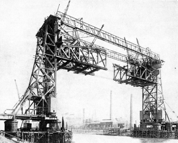
VERTICAL-LIFTSPAN in course of construction at Middlesbrough. It spans the River Tees between Yorkshire and Co. Durham. The completed span weighs about 2,500 tons.
In Great Britain the most familiar of all movable spans is the swing bridge, which may be seen in various places where navigable rivers have to be crossed at a relatively low level. At Newcastle-on-Tyne, for instance, the Swing Bridge provides direct road communication between the quays of Newcastle and the lower parts of Gateshead. The swing bridge takes many forms, but that best known consists of a simple revolving span mounted on a central pivot, with an equal channel on either side of it. Where the pivot is not situated centrally, the shorter arm of the swinging span generally needs to be counterweighted, unless there are other means for compensating for the weight of the longer arm.
The ordinary centrally pivoted swing bridge has an advantage which it shares with the Scherzer rolling bascule, namely, that it needs comparatively little power to set it in motion. It needs less, even, than the Scherzer bridge, as all its movements are in a horizontal plane and there is no increase in its resistance to the wind as it approaches the open position. Another advantage of the centrally pivoted swing bridge is that it allows two clear channels for shipping passing in opposite directions, one on either side of the artificial island supporting the pivot. Although vessels steaming in contrary directions cannot collide with one another while passing the open span they can, and sometimes do, collide with the artificial island supporting the swinging span itself.
Early French Examples
Though the swing bridge came into its own during the last century, the principle is quite old. As far back as the early seventeenth century it was known and applied. About 1625 the great pioneer Salomon de Caux built a remarkable swing bridge across a channel in the docks at Cherbourg, France. It had two swinging spans.
Another early swing bridge, also with two spans, is described by the French engineer Bernard Forest de Belidor, who wrote in 1813. In this the pivot took the form of a convex disk resting on a concave socket, with a ring of twelve balance wheels mounted outside it to check oscillation during the swinging process. This combination of convex and concave disks survives to this day in the design of many, swing bridges. The ends of the swinging arms were cut obliquely to the centre line of the bridge; one was grooved and the other tongued, so that the two spans came smoothly together and locked automatically. If the ends of the engaging spans, or the span and its approaches, were cut at right angles, it would be impossible to close the movable section, or to open it if its initial position was the closed one.
IN LONDON DOCKS, across the entrance lock (100 feet wide) to King George V Dock, is a large double-bascule bridge. This type of bridge is particularly suitable for spanning an entrance to one of the busiest dock systems in the world, for the leaves are opened easily to allow for the frequent passage of large ships. The Peninsular and Oriental liner Corfu, illustrated, has a gross tonnage of 14,170.
Some of the earliest iron swing bridges were installed in the old London Docks, completed in 1805. The modern swing bridge may take various forms, as does the modern bascule bridge. In addition to the ordinary centre bearing there is the rim bearing, wherein the weight of the swinging span is supported by a cylindrical drum revolving on rollers. For normal conditions, however, the centre bearing retains certain advantages over the rim bearing. It is extremely simple, and wheels are needed for balancing only. By concentrating the weight of the moving span on the single central bearing, the designer limits the possibility of damage by wear and tear, whereas in the rim bearing type this wear and tear is distributed over various moving parts, including the rollers or wheels and the circular rail on which they revolve. The central supporting pier does not have to be so large as in the rim bearing bridge. The central bearing is easier to build, and needs fewer delicately adjusted parts. Less friction is set up, and thus the span revolves more easily.
The rim bearing has shown certain advantages where unduly long spans are concerned, but now even long spans have been built on the central bearing principle; for example, the big swing bridge across the Sacramento River, in California. This structure has two decks, carrying a double-track railway on the lower deck and an 18-feet carriageway with two 5-feet sidewalks above. The swinging span is over 390 feet long, and the structure weighs 3,374 tons. At first it was proposed to install a rim bearing. At the time this form was generally considered essential for such a heavy bridge as this. Through lack of space the designer was compelled to substitute the ordinary central bearing, and the bridge has worked with complete success ever since.
There are, in various parts of Great Britain, several notable swing bridges carrying rail and road traffic. The Kincardine-on-Forth Bridge, and the London, Midland and Scottish Railway bridge over the Forth, near Alloa, also has a swinging span. The Eastern Counties, with their many waterways and expanses of flat country, also have several notable swing bridges, among which are the Cross Keys Bridge (rail and road) over the River Nene at Sutton Bridge, Lincs, and the railway bridges at Trowse (Norfolk), St. Olave’s and Beccles (Suffolk), and elsewhere. The retractable, or rolling bridge has not attained the same degree of popularity as the swing bridge. Mechanically it is inferior to the swing bridge and to the bascule bridge and whatever form it takes it is bound to be a complicated arrangement. There are several types of retractable bridge.
The Closed Position
In the closed position, the moving section forms a simple span across the intervening waterway. According to the design of the structure, this span may be drawn back, telescope fashion, into the fixed approach span; it may recede over the top of the fixed span, with the rear end upwards and the free end tilted downwards; the approach span may be run aside, traverser fashion, and the moving span proper run back into its place. Again, the moving span may be run back diagonally. A number of such structures have been built at various times in New York. Many years ago, the old London, Brighton and South Coast (now Southern) Railway built a retractable bridge across the River Arun near Arundel, Sussex.
An essentially modern development of the movable span is the vertical-lift bridge, in which the span over the channel rises at both ends between two high towers. Its application on a large scale belongs to our own time, though the principle was first developed during the latter part of the nineteenth century. R. Jacomb-Hood, as Engineer of the London, Brighton and South Coast Railway, built one of the first vertical lift spans across the Surrey Canal. Though this bridge was small the essential features were all there, counterweights falling at either end as the lifting span rose, span and counterweights being connected by cables passing over wheels at the tops of the towers. As span and counterweights are perfectly balanced, relatively little power is required for setting the lifting mechanism in motion. The vertical lift bridge has other things to recommend it. A greater economy of space is preserved than with the swing bridge or the bascule, and spans of considerable size may be made to move quite easily.
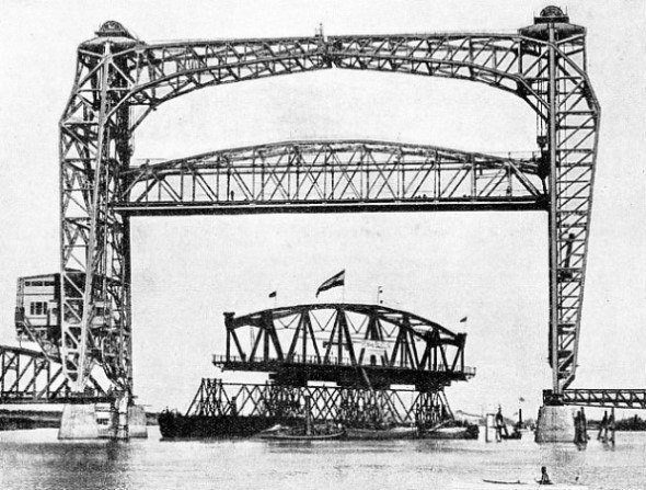
LIFTING SPAN of a bridge to be assembled at Spijkenisse, Holland, being towed down the River Maas underneath an existing vertical-lift bridge at Dordrecht. The navigable waterways of Holland are spanned by many different types of movable bridges.
It was in the 1890s that modern engineering skill presented to the world its first large vertical-lift bridge. An old swing bridge in Chicago was wrecked through a ship having collided with it. To replace it Dr. J. A. L. Waddell threw tradition to the winds and designed a vertical-lift structure on a scale never before attempted. On either side of the channel he erected a great steel tower, 217 feet high. The inner legs or members of these towers were vertical, with angle rails to guide the lifting span. The outer members had a slight batter, so that the towers tapered gradually from bottom to top. Between the towers he slung his lifting span, 130 feet long and carrying a 34-feet carriageway, flanked on either side by a footpath 7 feet wide.
At either end of the lifting span there were fixed eight steel wire cables passing upwards and over double-flanged wheels on the tops of the towers to the counterweights, which ran up and down inside the towers, lift-fashion. At the top and bottom of each tower Dr. Waddell provided four powerful hydraulic buffers for the reception of the moving span at the end of its upward or downward journey. The span and the counterweights were perfectly balanced so long as no weight was imposed upon the span. When fully opened, the span gave a clear headway of 155 feet. Propulsion was by means of a pair of 70 horse-power steam engines, connected by gearing to an 8-in. transverse shaft. On this shaft were mounted four drums, each 6 feet in diameter and carrying spiral grooves round which the hauling cables were wound. There were eight of these cables to each tower, four for raising the span and four for lowering it, and altogether the operating gear included no less than 8,000 feet of steel cable. In modern practice, such a figure would be excessive. The amount of cable used has been appreciably reduced with a corresponding drop in cost of maintenance. Waddell’s Chicago bridge was completed in 1894.
Since then, vertical-lift bridges have been erected in various parts of the world. There is a fine example in Rotterdam, Holland, carrying the main Amsterdam-Brussels railway line across the King’s Harbour.
Electric Control Preferred
One of Europe’s latest vertical-lift bridges may be seen outside Stockholm, Sweden. This, is not an individual structure, but takes the form of a span in the great new Arsta Bridge, carrying the electric railway line from Stockholm to Malmo and Goteborg across the channel called Arstaviken, lying just to the south of the city. Where the Arsta Bridge crosses the fairway, its designers put in a single lifting span.
The driver’s cabin on a movable bridge may have various positions, but it is always placed at a point from which the man in control has an uninterrupted view of rail or road, and of the waterway and its craft. In swing and vertical-lift bridges the control cabin is frequently placed on top of the moving section, midway between its extremities. Warning of a change in the position of the span can be given by visible and audible signals; where a roadway is involved, the ends of roadway can be closed by gates.
Various forms of motive power be applied to the operation of movable bridge spans. In the earliest forms, and in small examples to-day, this can be accomplished by a hand winch, so long as the structure is perfectly balanced and not subject to any undue resistance. Steam engines have been used, as in the first big lifting bridge at Chicago. They are thoroughly reliable and independent of any external source of power. On the other hand they need a good deal of attention, and steam has to be kept on the boilers all the time, whether the bridge is operating or not.
The internal combustion motor has its advantages. It is more economical than steam, and therefore more suitable for a bridge which is opened only a few times in each day. On the whole, the electric motor is the most satisfactory of all propulsive machines for this class of work, and most of the world’s large movable bridges are electrically operated to-day. The electric motor is clean, it is powerful, it is easy to control and, unlike the steam engine, it does not waste energy while it is at rest.
THE SCHERZER TYPE OF BASCULE BRIDGE is used to carry the London and North Eastern Railway tracks and a main road across the River Trent at Keadby, Lincolnshire. The bridge has an opening of 163 feet and contains about 3,000 tons of steel.


 The bascule bridge has many forms. In the typical small Dutch bridge, the lifting span is drawn up and balanced by a pair of overhead levers or beams, mounted rocker-