In the century which followed William Symington’s first application of a steam engine for driving a vessel’s paddle wheels enormous advances were made, not only in ship design but also in marine engineering
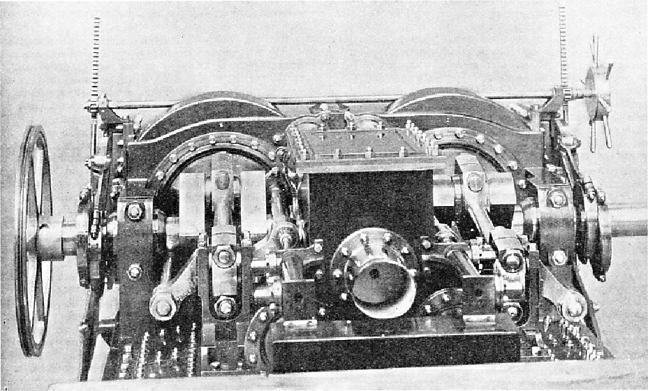
RETURN CONNECTING-ROD ENGINES were widely adopted in the middle of the nineteenth century, before high-speed vertical engines came into use. The illustration shows a model of the engines fitted in H.M.S. Wanderer, built in 1855. The engines had two cylinders with a diameter of 45 in. and a stroke of 24 in. With steam at a pressure of 20 lb. the engines ran at over 80 revolutions a minute and indicated over 700 horse-power.
AT first sight there appears to be little relationship between a modern steam-driven liner and one of the first steamships, of which models and prints survive in museums. The vessels have little in common except in so far as both use steam as a prime mover. The early steamship had paddle wheels driven by simple low-pressure engines. The modern liner has her several screws driven either by turbines or by electric motors through steam turbo-generators.
It was through the steam reciprocating engine that the revolution in ocean transport came into being during the last century. There are many tales, credible or apocryphal, about the origin of the steamship. A Spaniard, Blasco de Garay, is said to have built some sort of paddle boat in 1543 and to have tested her in the harbour of Barcelona. One account, not contemporary, said that
the paddles derived their power from “a cauldron of boiling water”. It is probable that de Garay did something unusual, even if it consisted only in using paddle wheels. The paddle wheel has been known for a long time. Papin (see the chapter “Origin of the Steam Engine”) suggested that the principle of the steam cylinder and piston might well be applied to paddle wheels for driving ships. It is unlikely that Papin would not have heard of such an idea if it had been applied before. Some early pioneer might have conceived the idea of applying the invention of Hero (see the chapter “Origin of the Steam Engine”) to a driving shaft, for during the Middle Ages Hero’s principle was incorporated in a machine for working a turnspit.
In 1705, the famous partners Savery and Newcomen designed an adaptation of the Newcomen engine for marine purposes, but there is no clear evidence that they applied it. In 1736, the inventor Jonathan Hulls designed a sternwheeler intended to serve as a tug. Hulls was ridiculed and died virtually penniless. John Fitch, in America, carried out a number of experiments on the Delaware River between 1787 and 1790, only to meet with the same discouraging reception as Hulls.
It was William Symington, the ingenious Scottish mining engineer, who built the first practical steamships. Symington’s name, however, does not occur in the first part of the story of the steamship. Patrick Miller, a rich Edinburgh banker, decided to devote his wealth and leisure to the advancement of mechanical knowledge. He built a two-hulled vessel, 60 feet long, at Leith, with paddle wheels, manually operated, between the hulls. His queer craft managed to beat a swift sailing cutter in the Firth of Forth, but great exertion was necessary to turn the cranks with effect. It was suggested to Miller that a steam engine was the obvious substitute for man-power. It was then that Miller got into touch with Symington, who had a reputation for ingenuity in things mechanical, and suggested to him the steam-driven paddle. On Dalswinton Loch (Dumfriesshire), which formed part of Miller’s extensive property, he had a small two-hulled paddle boat 25 feet long, and he gave Symington the task of providing her with an engine.
Symington installed a low-pressure boiler and an engine with two brass cylinders of 4 in. diameter. The engine developed about one horse-power and on October 14, 1788, in the presence of several hundred people, the tiny steamboat went through a number of successful manoeuvres. Encouraged by such a promising start, Miller and Symington produced a much larger vessel, also with two hulls, and propelled by a steam engine having two 18-in. cylinders and developing about 12 horse-power. This boat is said to have steamed along the Forth and Clyde Canal at a speed of about seven miles an hour. Then Symington and Miller quarrelled.
Symington took out a patent on his own account for a steamboat driven by a paddle wheel, and in this he succeeded in interesting the rich and influential Lord Dundas. The outcome was the building of the famous Charlotte Dundas of 1801. She was 56 feet long and 18 feet in the beam. As well as steaming alone at a speed equivalent to a fast trot on land, she showed herself capable of hauling two loaded 70-tons barges at three knots. Symington had at first intended to give her side paddles, but abandoned this idea under the impression that such an arrangement would cause too great a wash for canal traffic.
Experiments in U.S.A.
The Charlotte Dundas was a sternwheeler with a cylinder of 22 in. diameter and 4 feet stroke and a horizontal engine driving the single big wheel through a crankshaft on which was mounted the paddle wheel. It was alleged, however, that, despite the elimination of side wheels, the wash of the vessel brought down the canal banks. Whether this was true or not is still a matter for debate, but the first steamer of practical use was withdrawn, and lay in a creek off the canal for many years before she was broken up.
The trials of the Charlotte Dundas had attracted the attention of the American Robert Fulton, who carried out a number of experiments with steam propulsion on the River Seine, in France. To him belongs the credit for designing the first steamship in the world to be a commercial success and to work a regular service. She was the Clermont, a wooden side-wheel steamer fitted with a Boulton and Watt engine having bell-crank drive. She was about 140 feet long and was launched at Charles Browne’s Manhattan yard in the United States in the spring of 1807. The Boulton and Watt engine had a single cylinder of 24 in. diameter and 48 in. stroke.
The vessel was externally distinguished by a tall, thin smokestack and large side-wheels with no paddle-boxes. By August 1807 “Fulton’s Folly”, as sceptics called her, was ready for her trial trip, on which she astonished everybody. Fulton, however, saw that the paddles were setting up a certain amount of resistance because their blades dipped too low in the water. When he had rectified this he attained better results than ever.
On August 17, 1807, “Mr. Fulton’s ingenious steamboat” ran from New York to Albany, on the Hudson River, a distance of 150 miles, in thirty-two hours. After that she made many runs and enjoyed considerable patronage, so much so that Fulton produced a number of sister ships. The life of this first passenger steamer was long and illustrious, and she covered many miles on the Hudson.
MODEL OF A DOUBLE-HULLED VESSEL built in 1787 by Patrick Miller as an experiment in marine propulsion. Five paddle wheels were placed between the hulls and manually operated by capstans through bevel gearing. A voyage to Sweden was made, but the physical effort was exhausting. The ship was 100 feet long and displaced 255 tons.
The first passenger steamer in Europe appeared on the River Clyde. Henry Bell was a hotel owner at Helensburgh, on the lower Clyde near Dumbarton, and he watched with interest the successive experiments of Symington and Fulton. Before 1805, with the support of Lord Nelson, he had tried to impress the Admiralty with the practicability of steam navigation. But even with so distinguished a sponsorship as this the Admiralty was not persuaded. Bell, therefore, determined to build a pleasure steamer to be worked as an adjunct to his hotel on the Clyde. Thus, during 1811-12, was the historic Comet born. She was only 40 ft. 3 in. long and 11 ft. 3 in. wide, drawing 5½ feet of water. Her tonnage was a little over 25.
Bell installed a small 4 horse-power steam engine driving four paddle wheels, two on either side, with a single elongated paddlebox covering each couple. Each paddle wheel had four blades, similar to those of an ordinary canoe paddle, set crosswise. Bell found that this arrangement did not answer at all well. So he removed one pair of paddles, after which the vessel behaved admirably, making her first public trips on the Clyde in August 1812.
In 1816 the Comet was plying on the Firth of Forth. Two years later she was set to work between Glasgow and the West Highlands, going as far north as Fort William. It was on this service that she met her end, for in December 1820 she ran aground off Crinan, Argyll, and broke her back. Her forward part was lost, but the after part, with the engines, remained fast on the rocks. From it the engines were salved, and they may now be seen at the Science Museum, South Kensington.
At first, steam engines were looked upon merely as a form of auxiliary power —at any rate for seagoing ships. The Savannah, a typical early auxiliary, was the first ship equipped with engines to cross the Atlantic, which she did in 1819, taking twenty-six days. To say that she steamed across the Atlantic, on the other hand, is not correct, for she made almost the whole of the crossing under sail. She ran her engines at either end of the trip, the paddle wheels being shipped most of the time.
In 1826 J. H. and J. Duke, of Dover, built the Calpe, a schooner-rigged paddle steamer — a genuine steamship, not an auxiliary —of 438 tons. She was sold in the same year to the Dutch Navy, in which she became the Curacao. She had independent engines driving the two paddle wheels. Between 1827 and 1829 she crossed the Atlantic several times between Holland and the Dutch colony from which she took her name.
In 1833 the Royal William, launched at Quebec but fitted with engines from England, crossed the North Atlantic from Pictou, N.S., to Gravesend in twenty-two days. The comparatively short distance between Europe and America was fraught with far greater hazards than much longer coastwise journeys. As far back as 1825 Captain Johnson received £10,000 for making the first voyage under steam from England (Falmouth) to India by way of the Cape of Good Hope with the paddle steamer Enterprise.
DOUBLE PISTON-ROD STEEPLE ENGINES are represented by this model of several built for shallow-draught river steamers in 1850. Developing 30 horse-power, the full-size engines had single cylinders of diameter, with a stroke of 3 ft. 6 in. The vertical cylinder was placed below the crankshaft and the two piston rods passed one on either side of the crankshaft.
Then, in 1838, a wonderful double event took place on the Atlantic, in which figured two steamers, the Sirius and the Great Western. The Sirius had been built by Menzies and Co., of Leith, in 1837, and her normal work consisted of plying across the Irish Sea between Great Britain and Ireland in the service of the St. George’s (later City of Cork) Steam Packet Company. She had a gross tonnage of 703 and a length of 178 feet. Her paddle wheels had a diameter of 24 feet and were driven by cylinders of 60 in. diameter using steam at a pressure of 15 lb. per sq. in.
The Great Western was designed by I. K. Brunel, who proposed to extend the services of the Great Western Railway across the Atlantic. She was a giant compared with the little Sirius, having a gross tonnage of 1,320. Her wooden hull was 236 feet long and 59 feet wide over the paddleboxes, drawing 16 feet of water. She was engined by Maudslay, Sons and Field, the engines being of 750 nominal horse-power and using steam at a pressure of 5 lb. per sq. In.
In 1838 the Sirius was chartered by the British and American Steam Navigation Company. On April 4 she left Queenstown (Cobh) for New York, commanded by Lieut. R. Roberts, R.N. This little steamer carried ninety-four passengers, in addition to stores and 450 tons of coal.
Three days later the big Great Western left Bristol, bound for the same destination as the Sirius. The Sirius reached New York on April 23, and the Great Western steamed into port four hours after her.
The Great Western was succeeded by another large Brunel steamship, the Great Britain, one of the loveliest ships that ever sailed. She might be described as the forerunner of the modern Atlantic liner, for though originally intended to be a paddler, she was finally built as a screw steamer. This was the effect of a visit paid to Bristol by the Archimedes, one of the first screw steamers. For many years after this, however, paddlers continued to be built for the Atlantic crossing, and these included the first
Cunard liners. The Great Britain had a displacement of 3,618 tons and her engines had four 88-in. by 72.-in. cylinders, driving a six-bladed propeller. She was laid down at Bristol in 1839 and was completed in 1843. She started for New York from Liverpool on July 26, 1845, making an average speed of over nine knots. In addition to being the first large screw steamer, the Great Britain was also the first big vessel to have an iron hull.
THE FIRST LARGE SCREW STEAMER was the Great Britain, a vessel of 3,618 tons, built in 1843. Her engines had four cylinders with a diameter of 88 in. and a stroke of 72 in. On July 26, 1845, she left Liverpool for New York, making an average speed of over nine knots. Originally rigged with six masts, she was later reduced to three. In 1882 her engines were removed and she ended her days as a coal hulk.
“Grasshopper” Engines
All the earliest steamships were driven by paddles, but the principle of the screw had been invented years before it was applied to a steamer. Among the many inventions of Joseph Bramah was a screw propeller, for which he took out a patent in 1784. Bramah’s screw was before its time, and it was not until 1836 that F. P. (later Sir F. P.) Smith and John Ericsson, a Swede, working independently, applied the screw with success.
The Archimedes was a 237-tons schooner-rigged steamer, fitted with the new screw propeller patented by F. P. Smith. She had two engines geared to a single propeller shaft, and had a maximum speed of nine knots.
Symington adapted the horizontal engine for driving the paddle wheel of the Charlotte Dundas, and this arrangement persists in shallow-draught stern-wheelers on the rivers of many countries. The beam engine, however, was the type most frequently adopted, or rather modified, for the steamship in early days. The beam was generally placed over the crank in the early American steamers, such as those on the Hudson, and it is still to be seen on other American rivers. Continental and British practice favoured the modification known as the side-lever engine.
In this the designers placed the beam under the crank on a fulcrum mounted-between the supports of the crankshaft and the cylinders or cylinder. The connecting rod was attached to one end of the beam. From the opposite end side rods were coupled to a crosshead which, moving up and down between slide bars above the cylinder, was attached to the piston rod in the usual way. The side-lever engine was an efficient design for its day, though it took up a good deal of space as compared with the later direct-acting engines. There were several variations. In the “grasshopper” engine the fulcrum of the beam was at the end opposite to the piston connexion, the connecting rod coming down between, so that the stroke of the crank was shorter than that of the piston. The steeple engine had no beam, but was direct-acting, with a connecting rod returned backwards, the crankshaft being just above the top of the vertical cylinder.
Steam made its appearance in the British Navy in 1821 with the advent of H.M.S. Monkey, of 212 tons, built at Rotherhithe (London) and having a two-cylinder Boulton and Watt engine of 80 nominal horsepower. She was followed by H.M.S. Active, with similar engines from the same firm. The cylinders had a diameter of 35½ in. and a stroke of 42 in. The engines ran at a normal maximum speed of 26½ revolutions a minute.
SIDE-LEVER ENGINES drove the paddle wheels of H.M.S. Dee, a mail packet built in 1827. This working model is said to have been made by Henry Maudslay. The cylinders of the Dee’s engines had a diameter of 54 in. and a stroke of 5 feet.
In its early days the marine engine suffered through its own success. This sounds paradoxical, but the simplicity and smooth working of the old side-lever engine, receiving steam from simple low-pressure rectangular flue boilers, was such that the modern high-pressure engine was a rather long time in coming to replace it. The marine engine did not develop nearly so rapidly as the locomotive.
The paddle wheel, however, had numerous disadvantages, more especially for seagoing vessels. It was affected by the variation of draught, according to whether the vessel was in cargo or in ballast. It was not suitable for the application of higher degrees of power. The paddleboxes set up considerable resistance to wind in a heavily laden ship, and the whole arrangement was exceedingly vulnerable in a naval vessel. Much of the machinery had to be above the waterline, taking up valuable space.
For this reason the side-lever engine gradually fell into disuse. In its place Maudslay produced the double-cylinder direct-acting engine, in which two cylinders were placed side by side under the crankshaft, with their piston rods connected with a T-shaped crosshead above. The tail of the T passed down between the cylinders and had a crosshead at its lower end, to which the connecting rod was attached.
Maudslay, Sons and Field also produced an oscillating engine in 1828 which they fitted to the paddle steamer Endeavour. The use of oscillating cjdinders was taken up and improved upon by John Penn. The oscillating engine, though a slow-speed engine, had the advantage of great simplicity. The cylinder was carried on trunnion bearings directly under the crank and no connecting rod was required, the piston rod being coupled directly to the crank. Penn’s oscillating engines survive in certain old paddlers.
Geared Propellers
The introduction of the screw propeller as a substitute for the paddle gave rise to considerable modification in the layout of the ordinary marine engine. First and foremost, the screw had to be driven at a much higher speed than the paddle wheel and this presented difficulties with the slow low-pressure engines then in use. At first gearing solved the problem, but this was abandoned as soon as the increase of pressure and of engine speed became general. While the direct-acting engines of the later paddle steamers had been either vertical or diagonal, those of the early screw steamers had to be horizontal, set at right angles to the centre line of the ship.
In such a position the length of the horizontal engine was seriously limited. John Penn overcame this drawback by dispensing with the piston rod altogether — in the same way as the connecting rod had been eliminated in the oscillating engine — and fitting a large hollow “trunk” to the piston. This trunk passed through steamtight stuffing boxes on the cylinder covers. The connecting rod was coupled to the piston by means of a journal in the trunk at the middle of the piston itself. In the days of low pressures this arrangement answered well. The introduction of much higher pressures caused this type of engine to become obsolete because of the difficulty of keeping the trunk stuffing boxes steamtight.
In the return connecting-rod engine, each piston had two rods, one passing above and one below the crankshaft, a crosshead being mounted on the side opposite to the cylinder, whence the connecting rod worked back to the crankshaft. This design had the disadvantage of necessitating two stuffing boxes to each cylinder, and complicated the design of the piston. The defect was remedied after a time by providing one piston rod only, with a crosshead on the cylinder side of the crankshaft, this being connected with the crosshead on the other side by two rods, one above and one below the shaft. The return connecting-rod engine was widely adopted before the high-speed vertical engine came into use.
During the 1850s, screw steamers for naval and mercantile duties were generally fitted with horizontal engines using steam at a pressure of 20 lb. to 25 lb. per sq. in. As pressures rose in successive designs, the old rectangular boilers with simple flues were retained for a while, internal stays being fitted to enable them to withstand the increased pressure. Improvements were made in the design of condensers, and fuel economy was promoted by the provision of steam jackets to the cylinders. In ships of the British Navy during the 1860s, a pressure of 30 lb. to 35 lb. per sq. in. remained usual.
The perfecting of the condenser played a large part in enabling the designers of marine engines to increase their working pressures to figures far in advance of those in the early steamers. The old rectangular boilers were replaced by cylindrical boilers of much greater strength. Heating surface was increased by the introduction of the multitubular boiler, which had been first applied to locomotives as far back as the end of the 1820s.
Triple Expansion
Further economies were effected by the introduction of superheaters, in which the steam was dried and its pressure materially increased before it passed to the cylinders.
Increased pressure enabled compound, or double-expansion engines to be used, in which the steam exhausted by the high-pressure cylinder did further work in the low-pressure cylinder before passing to the condenser. The early compound engines, as used in naval vessels after 1870, used steam at a pressure of about 60 lb. per sq. in. The introduction and popularity of the
vertical marine engine effected a considerable simplification of engine-room arrangements. The vertical engine is simplicity itself, compared with the complicated horizontal return connecting-rod engine. With twin-screw vessels, two sets of relatively small engines could be provided, one on either side of the ship’s centre line, with a watertight bulkhead between them.
As pressures increased, so did the diameter of the low-pressure cylinder. As an alternative, the designers of marine engines provided two low-pressure cylinders to the one high-pressure, thus producing the three-cylinder compound engine. With the pressure rising to 100 lb. and over, it was but a short step from the compound engine to the triple-expansion engine, in which the high-pressure cylinder exhausts into a medium-pressure cylinder, which in turn exhausts into the low-pressure cylinder, this last exhausting to the condenser.
The first ship to be propelled by a triple-expansion engine appeared in 1874. This vessel, the Propontis, was equipped with water tube boilers of an early design, delivering steam at a pressure of 150 lb. per sq. In.
A. C. Kirk, of Napier & Sons, Glasgow, was responsible for the efficient engines. Unfortunately, the boilers were not so satisfactory and the reputation of the Propontis suffered. Not until 1881 did the triple-expansion engine reappear, being fitted by Kirk this time to the Aberdeen, a ship intended for the China and Australian trade. The Aberdeen was so successful that the future of the triple-expansion engine was thereupon assured. Quadruple-expansion engines came later but they had a somewhat limited field.
With the triple-expansion engine we emerge from the early phases in the history of marine engineering. Turbine propulsion of steamers, though it originated many years ago, is essentially a feature of modern times. It was with the reciprocating engine that the steamship established herself, in the nineteenth century, and with the reciprocating engine alone.
MODIFIED SIDE-LEVER ENGINE. This working model represents an arrangement in which the pair of cylinders is placed fore and aft instead of athwartships. One cylinder drives the crankshaft by a pair of side levers, the other, arranged under the crankshaft, drives directly by side rods.