For the transmission of power beneath the streets of London there is a network of hydraulic mains, carrying water at a pressure of 700 lb. per square inch. This hydraulic power is used for many different purposes, from driving motors to operating lifts and similar mechanisms
THE TOWER SUBWAY carries water and hydraulic pressure mains beneath the River Thames. It was built in 1868 as a railway tube by the engineers Barlow and James Greathead but proved unsatisfactory as such. It has a diameter of 7 feet. The hydraulic pressure main is on the left.
BENEATH the streets of London there lies a network of water pipes carrying the enormous pressure of 700 lb. to the square inch. Other great cities have similar networks. The great London system, however, is not intended to supply water for drinking and similar domestic purposes. The hydraulic main is used solely for the transmission of power, in much the same way as the electric cable carries energy from the great generating stations to the users of electricity throughout the cities and towns of the world.
Hydraulic power may be described as the “strong man” of the city with an output of energy that is concentrated on the lifting of heavy loads. The secret of the utility of the hydraulic mains lies in the fact that water is virtually incompressible, and is therefore an ideal agent for transmitting power from one place to another. In London, water power is transmitted through a vast
network of hydraulic mains to thousands of hotels, shops, offices, private residences, docks and factories.
Hydraulic power plays an important part in the operations of lifts and cranes, but there are many other purposes for which the great pressure of the water is used in industry and even in the home. Among the many devices that take power from the hydraulic mains and turn it into mechanical energy is the inexpensive and reliable water motor used for driving machinery of all kinds. Its use is limited, however, to instances where a heavy fire risk might attend the use of an electric motor.
Water motors are built in different types, some of which resemble, on a smaller scale, the giant turbines that harness the power of Niagara and other waterways for the generation of electricity. The type of water motor best suited for operation by pressure from the hydraulic mains is the Pelton wheel, which is built in all sizes from ¼ horsepower to nearly 20,000 horse-power. The large Pelton Wheels are not generally run from city hydraulic mains; they belong rather to great power schemes.
The principle of operation is the same in all instances, but the smaller Pelton wheels taking water from the hydraulic mains are generally geared to reduce the enormous speed. The Pelton wheel consists of a disk, mounted on an axle, and fitted round the circumference with a ring of “buckets” into which a jet of water is directed by a specially shaped nozzle. The interior of the nozzle is contracted gradually towards the outlet so that the pressure of the water is converted to velocity before its discharge against the buckets of the wheel or runner. On striking the buckets the velocity energy of the jet is transferred to the runner, which revolves at high speed. The shape of the buckets is of great importance, and each may be compared with a pair of cupped hands held side by side bolted by the “wrists” to the wheel-disk or runner. The jet, cleared by the gap over the ends of the “little fingers” as the buckets revolve, impinges against the hollow “palms”, glancing off to right and left over the “thumbs”. When the water swirls out from either side of the wheel it has lost its energy and falls to the bottom of the casing, from which it drains away.
The speed control of the Pelton wheel is especially ingenious. The velocity of the jet must not be lessened by curtailing the water supply from the main, but the area of nozzle is lessened by pushing forward, from inside the pipe, a streamlined plug or “spear”. The water flows round the spearhead and coalesces into an annular jet of smaller diameter but with undiminished velocity. The spear may be controlled by a handwheel or automatic governor gear, and in large machines is supplemented by a movable deflector, attached to the nozzle, capable of directing the jet clear of the buckets.
A water motor of entirely different type is incorporated in the hydraulic capstan used for hauling railway wagons in sidings or yards or for similar purposes in workshops and factories. The capstans worked from London’s hydraulic mains generally exert a pull of one ton on the hauling rope and are capable of drawing, along a level track, trains of wagons weighing between 50 and 100 tons. The capstan is mounted above a sectional steel chequer plate, through which also protrudes the treadle of a foot-operated control valve. The plates are removable and the capstan can be swung on trunnions to facilitate adjustment or repairs to the hydraulic engine at its base. This engine consists of three radial cylinders arranged round the capstan shaft. The cylinders contain rams connected with a common crank and valves that control the supply of water; the machine is the converse of a pump, in which the water does the driving instead of being driven.
For Cleaning Carpets
Hydraulic power provides a convenient method for raising water used for drinking or other purposes and also for pumping water from basements and similar places subject to flooding. For raising water from artesian wells by hydraulic power a cylinder is used in which a ram moves up and down automatically. The valves admitting water to the cylinder are operated by tappets and the end of the ram is attached to an overhead crosshead provided with two rods running in guides. The lower ends of the guide rods are secured to another crosshead and this carries the upper end of the pump rod leading down into the borehole of the well. The operation of the pump is automatic, being controlled by float gear in the cistern.
Another type of hydraulic pump works on the ejector principle. A jet of high-pressure water from the hydraulic main is arranged just below a narrow portion of a vertical water pipe. Some of the velocity of the jet water is imparted to the water in the pipe, which is thus raised to the required level. By the use of a float this type of apparatus can be made entirely automatic. A water jet may also be used to create a vacuum.
For the production of a more powerful suction, however, a jet of high pressure is required such as that obtained from a hydraulic main. It is not generally known that in many of the shops, theatres, hotels and private houses in London the lift service is augmented by the hydraulic vacuum cleaner. It is necessary only to connect the end of a long flexible pipe to the hydraulic ejector apparatus and use the various nozzles and brushes on carpets, walls and furniture. A great advantage of this method of cleaning, apart from its silent operation, is that all dirt and grit are discharged directly into the drains. Yet another application of the hydraulic main is for the purpose of organ blowing. The apparatus is somewhat similar to that for pumping, and the ram is directly connected to the organ bellows.
The peril of fire is always present in every large city and in this connexion London has special problems to face. One of the most important safeguards against fire in warehouses or other buildings is the injector fire hydrant supplied with water from the ordinary mains or from tanks and with power from the hydraulic mains. The large volume of low-pressure water is brought under pressure hydraulically, and is delivered to hose hydrants or sprinkler systems as required. A hydraulic injector fire hydrant, in its largest form, is capable of delivering water at a suitable pressure for fire fighting at the rate of 650 gallons a minute. It is preferable to use this system, rather than the hydraulic main direct, for fire extinguishing. The main is primarily a power line, not a water supply.
PUMPING MACHINERY near the southern approach of Tower Bridge provides hydraulic power for raising and lowering the bascules of the bridge and for working the lifts which carry pedestrians up the towers to the overhead footway (see pages 575-580). The photograph shows one of the two sets of pumping engines.
The enormous power of the hydraulic ram, as used for cranes and lifts, can also be applied in presses for forging, stamping or flanging. There are hundreds of such presses in use throughout warehouses for baling cloth and paper, and for compressing scrap metal and other materials to facilitate transport.
In some instances it is necessary to use a higher pressure than the 700 lb. per sq. in. of the hydraulic mains. The additional pressure, up to 6 tons per sq. in. (equivalent to a waterhead 30,000 feet high) is obtained by the use of a hydraulic intensifier that may perhaps best be described as an arrangement of hydraulic leverage. A large volume of water at 700 lb. per sq. in. is used, by means of differential rams, to discharge a smaller volume at an increased pressure. The converse of this principle is seen in hydraulic car jacks and similar apparatus.
A powerful small-bore pump is used to force water into a ram-cylinder of much greater bore. A moderate pressure on the pump plunger is sufficient to raise the ram through a shorter distance than the stroke of the pump, but with greatly increased power. The leverage or increase in power is dependent on the respective sizes of the pump plunger and of the ram. Thus a pump with a plunger of 1 in. diameter on which a pressure of 550 lb. is exerted will cause a ram of 4 in. diameter to exert a force of 8,800 lb, the movement of the plunger being, however, sixteen times as much as that of the ram.
Water power in London is controlled by the London Hydraulic Power Company, incorporated by Acts of Parliament between 1871 and 1903. The company supplies water at a pressure of 700 lb. per sq. in., day and night, all the year round, through some 180 miles of cast-iron and steel hydraulic mains laid under the streets of London.
This great labyrinth of power lines was not built in weeks or months, and the gradual spread of the silent tubes has been going on for more than half a century. The number of gallons of water pumped each week through the company’s mains in 1893 was 6,500,000; water pumped through the mains in 1933 averaged 32,000,000 gallons weekly. The mains are carried over the Thames at Vauxhall Bridge, Waterloo Bridge and Southwark Bridge. They cross under the river through Rotherhithe Tunnel and the Tower Subway beneath the Pool of London. The Tower Subway, now the property of the London Hydraulic Power Company, is of special interest as the first tube railway in the world.
Converted Tube Railway
This tunnel was designed by Peter William Barlow and was built by his son, P. W. Barlow, and James Henry Greathead. Work was begun in 1868 and the subway was finished in less than twelve months. Shafts were sunk at Tower Hill and at Vine Street on the Surrey side of the river. The tunnel was lined with cast-iron cylinders and from either end it was sloped down towards the centre to assist in the starting and stopping of the passenger car. An underground waiting room was provided at the foot of either shaft, equipped with lifts driven by small steam engines. In the bottom of the tube rails were laid on which ran a cable-operated carriage seating fourteen passengers. The diameter of the tunnel is 7 feet and its length 1,340 feet.
The cable car ran for only a few months and proved unsatisfactory. It was accordingly removed, and a pavement replaced the rails. The lifts gave place to wooden staircases and served the subway until it was closed, on the completion of the Tower Bridge, on June 30, 1894. The purchase of the subway by the London Hydraulic Power Co. followed. In addition to the high-pressure mains, the tunnel accommodates also two large mains of the Metropolitan Water Board. The northern entrance to the subway, on Tower Hill, is surmounted by a handsome circular tower, well in keeping with its neighbour, the Tower of London.
HYDRAULIC ACCUMULATOR for the automatic regulation of the pump delivery, to ensure a constant supply to the Tower Bridge equipment at the required pressure. When the pumps deliver more water than is needed, the surplus is forced into the ram and cylinder, causing the weighted casing to rise and the pumps to reduce speed. When more power is required the casing falls and supplements the pumps.
Hydraulic power is supplied through London’s mains by five pumping stations, three on the banks of the Thames at Vauxhall, Blaclcfriars and Wapping, another at Rotherhithe close to the Albion Dock, and the fifth at City Road, to the extreme north of the mains network. The. pumping stations are thus disposed at strategic points in the most important areas of the city.
All five pumping stations of the London Hydraulic Power Company are similar in general arrangement. A description of the Wapping plant may therefore be taken as typical of them all. The output of the Wapping plant, however, places it amongst the largest hydraulic pumping stations in the world.
The Wapping pumping plant comprises a Parsons steam turbine coupled to a large turbo-pump with an output of 1,000 gallons a minute. This turbo-set is arranged to take a large proportion of the constant load of the station. In addition to the turbine machinery there are six triple-expansion steam pumping engines with a capacity of 1,500 gallons a minute.
These engines are automatically controlled by the rise and fall of a hydraulic accumulator. This is one of the most important devices in the station, and it is used to control automatically the output of the pumps, to ensure a constant supply to the mains at over 700 lb. per square inch. The supply from Wapping is delivered at 850 lb. per square inch to allow for pressure drop in the mains due to friction in the pipes and other causes. The design of hydraulic accumulators varies, but the main principle of their operation is the same, irrespective of weight and size. A heavy cast-iron cylinder, fixed in a massive baseplate, contains a large ram and is provided with stuffing box suitably packed to prevent leakage of water. On this ram is fitted a crosshead from which is slung an enormous sheet-steel casing provided with guides. The casing is loaded with ballast in the form of scrap iron or other material. The lower end of the cylinder is provided with an inlet and outlet pipe connecting with the pumping plant and and hydraulic mains.
Filtered Water
When the pumps are delivering more water than the cranes and other hydraulic machines can use, the surplus is forced into the ram and cylinder. As more and more water is pumped into the accumulator, the enormous weight slowly rises but at the same time the speed of the pumps is gradually reduced. The speed is automatically controlled by tappet gear actuating the steam throttle valves on the pumping engines.
When, however, the demand for hydraulic power, is heavy, the accumulator supplements the pumps and, as the weighted casing falls, pumping is speeded up to cope with consumers’ requirements. The great accumulators at Wapping are 10 feet in diameter and 50 feet high, and they carry loads of approximately 120 tons.
Steam is supplied to the Wapping pumping engines at a pressure of 150 lb. by three boilers equipped with automatic stokers of the chain-grate type.
The pumping station is situated close to the London Docks and coaling is merely a matter of raising the fuel by grab from barges. The coal is conveyed automatically to the chain grates in the boiler room.
Water for supply to the mains is not pumped directly into the hydraulic system. It is first drawn by powerful circulating pumps from the Shadwell Basin in the London Docks, and is then delivered through filtering screens to overhead storage tanks at the station. From these tanks the filtered water flows by gravity to the pumps for final distribution, and is then forced into the power mains under enormous pressure.
Over 3,000 gallons of water are delivered into the mains every minute at a pressure of 850 lb. per square inch. This is equivalent to shooting more than 10 tons of water each minute to a height of no less than 2,000 feet.
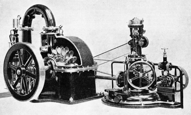
MODEL OF A PELTON WHEEL, or hydraulic turbine, with part of the casing cut away to show the buckets on the disk keyed to the main shaft. The speed is controlled, under varying load, by a servomotor nozzle regulator actuated by a centrifugal governor. The servomotor is mounted on a tank base which serves as an oil reservoir, pressure being provided by a rotary pump driven by a belt from the turbine shaft.


 The cable car ran for only a few months and proved unsatisfactory. It was accordingly removed, and a pavement replaced the rails. The lifts gave place to wooden staircases and served the subway until it was closed, on the completion of the Tower Bridge, on June 30, 1894. The purchase of the subway by the London Hydraulic Power Co. followed. In addition to the high-