The River Thames, from its source to Teddington, Middlesex, is controlled by the Thames Conservancy, which is responsible for the maintenance of locks, weirs and other works, as well as for the control of the water level and of navigation
TO REDUCE THE FLOODS two roller sluices, each 35 feet wide, were added to Teddington Weir, the lowest weir on the Thames, as part of a large improvement scheme completed in 1935.
PROBABLY few rivers have been more subjected to control by engineers than the Thames. In recent years important works have been carried out by the Conservators of the River Thames, who control the river and its tributaries from the source to Teddington, Middlesex. The area of the catchment basin is 3,812 square miles. Below Teddington there is only one lock, the half-tide lock at Richmond, Surrey. From Teddington to the sea the river is controlled by the Port of London Authority. The powers of the Thames Conservancy include the maintenance of engineering works, dredging, the regulation of water levels, the control of navigation and river purification.
Although the locks and weirs do not compare in size with the huge works built in other parts of the world, the newer Thames structures are fine examples of modern engineering. The older locks and weirs are maintained in excellent condition.
The total fall of the river from the source at Thames Head, in Gloucestershire, to Teddington is 342 feet in a distance of about 146 statute miles. There are forty-seven reaches, forty-nine locks, forty-four main weirs, forty-three subsidiary weirs and fifty-one overfalls.
The locks are spread over a distance of 124¼ miles and differ considerably in size. Thus at Teddington there are three locks, the smallest of which is only 52 feet long by 6 feet wide. The largest, the barge lock, is 650 feet long by 25 feet wide. The remaining one, the old lock, is 177 ft. 5 in. long by 24 ft. 11 in. wide. Representative dimensions for the other locks below Iffley, near Oxford, are 135 feet long by 18 feet wide, and above Iffley 114 feet long by 15 feet wide. There is a weir or system of weirs adjacent to every lock. The newer locks and weirs are on the sites of previous works; this often causes difficulties when piles are being driven for new structures. Masses of masonry or timberwork built in the past are discovered buried in the bed of the river after work has begun and the steel piles have to be driven through them.
So important was the Thames as a highway and as a water supply that centuries ago the stream was controlled by engineering works. Weirs were built to impound the water and to supply watermills. An opening called a “flash” pass was built into the weir, to allow boats to be hauled through. When a vessel required a passage the gates were opened and the vessel often had to be hauled through by men. The next step to facilitate navigation was the building of locks to by-pass the weirs. The locks were cut across bends in the bank adjacent to the weirs so that the land on the river side of the lock became an island, or the channel on one side of an island was deepened and a lock was built there. From time to time, particularly in recent years, old locks and weirs
have been replaced by new ones, the river has been widened and new channels have been cut. For many years past the design has been standardized as far as possible.
THE NEW WEIR AT MOLESEY forms part of an improvement scheme recently carried out by the Conservators of the River Thames. The weir (of which this is the upstream side) contains three roller sluices, each 8 ft. 6 in. deep and with a clear span of 25 feet. These sluices are operated from a gangway carried across the weir.
The durable and reliable type of weir has tackle that can be operated by one man, and all moving parts are simple and strong so that they are maintained with the minimum of skilled attention and repair. The tackle is generally of two different types. Gates which open by sliding vertically between guides are placed in the middle portion of the weir with sills from six to eight feet below the level of summer headwater (the water on the upstream side of the weir), the tops of the closed gates being at headwater level. On either side of the gates are lengths of weir, the sills of which are higher than those of the middle part. These flanks are fitted with small wooden paddles which close the opening up to the level of summer headwater.
It is more convenient to take out or put in the wooden paddles than to raise or lower the deep sill gates. The purpose of this secondary tackle is to provide easy means of keeping the head water at normal level in ordinary conditions without causing the fluctuation of level that would follow if the main gates were operated when variations in the flow of the river were small. The main gates are opened in times of flood. Use of the secondary tackle also distributes the total flow over a greater length than if the entire flow was confined solely to the gap between the main gates, and causes less disturbance to navigation.
Steel Piling Displaces Timber
The foundations of this type of weir consist of a massive apron of concrete protected on the upstream and downstream sides by rows of interlocking steel piling connected by stout cross tie rods at intervals of about 6 feet. These piles form a watertight screen and also protect the ground under the apron from erosion. Erosion does not occur frequently at the upstream edge of the apron except when the weir is not square to the line of stream, but there is always a strong action at the downstream edge, so that the piles at the side have to be much longer than those on the upstream side. Erosion is so strong that the bed of the river has been scoured in places to a depth of more than 25 feet. To protect the bed of the weir pool, sacks filled with concrete are dropped through the water to form a protective apron. Sometimes these sacks have been rolled out of position by the force of the current, and one-ton blocks of concrete, nearly cubical in shape, have had to be used.
PART OF THE THAMES IMPROVEMENT SCHEME, completed by the Conservators in 1935, was an increase in the weir capacities at Teddingon, Molesey and Sunbury. This illustration shows the two supplementary roller sluices which were added to Teddington Weir. Before the work could be begun, the entire site had to be enclosed in a cofferdam of sheet steel piling. The foundations, abutments and central pier of the weir were built of mass concrete and the superstructure of reinforced concrete.
The frames of the weir are of steel, and the gangway is generally of reinforced concrete. The deep sill gates are either of timber strengthened by iron bands or of steel. Gates up to 6 feet deep are made in one unit; greater depths are provided by adding a second unit.
In the paddle section of the weir the paddles rest against vertical rimers (square posts). The bottom ends of the rimers fit into sockets in a cast-iron sill, and the tops bear against a beam which forms the upstream edge of the gangway. After the paddles have been removed the posts can be taken out, leaving an uninterrupted opening between the steel frames.
A weir is built in one operation if there is an alternative channel for the flow of the water. If there is only one channel it would be dangerous in flood conditions to obstruct it by a dam and therefore the weir is built one-half at a time.
Steel piling has displaced timber in the building of the locks. When Chertsey Lock was rebuilt in 1913 the advantage of this method was proved. The old timber lock had a length of 170 ft. 5 in. and the new one was to be increased to 201 feet. The total width over the timber sides of the lock was 22 ft. 6 in. Two rows of steel piling to hold up the ground during construction were driven at 25 ft. 6 in. centres apart, one on either side of the lock, which was kept open to traffic. When the back piles had been driven they were strutted apart, the lock was closed and the old work was dismantled.
EXTENSIVE FLOODS sometimes occur in winter months when the River Thames overflows its banks. This photograph was taken near Sonning, Berkshire, in March 1937. The Conservators are continually undertaking engineering works to minimize the risks of flood.
The rectangular enclosure of steel piling was much more watertight than timber piling, and in comparison reduced the leakage to be dealt with by pumps to about one-third of that experienced with timber piles. The two rows of steel piles formed the side wall for the lock when held rigidly at the bottom by a concrete invert. The piles were anchored back by 1½-in. tie rods, passed through each pile near the top and fixed by a washer and nut, the other end of the tie rod being fastened to a concrete anchor
block set in the ground away from the face of the lock side. The exposed faces of the piles were encased with concrete 18 in. Thick.
The lock gates for new locks or for replacements consist of a framework made up of a heel post, a mitre post, top and bottom rails and a series of intermediate rails, all of greenheart or jarrah fastened with iron straps and bolts. Greenheart timber, from British and Dutch Guiana, is a hardwood which resists the attacks of water worms and lasts for a long time; jarrah is a Western Australian wood, not quite so heavy as greenheart, but remarkably durable. It can be obtained in larger pieces than greenheart: hence its suitability for heavy work. The frames are sheathed with deal planking. A gangway about 3 feet wide is built by bearing timbers on T-irons bolted to the top rail and decked over with planks.
In most gates the mitre and heel posts carry above the top rail and are tenoned and strapped to a balance beam about 30 feet long, which serves for the opening lever of the gate. At the larger locks, or where there is not room for the beam, a grooved cast-iron quadrant is fixed to the top rail to operate the gate. The quadrant is turned by a wire rope, fastened to either end, and the middle part of the rope winds round a grooved drum. The drum is worked by a shaft and bevel gearing housed in a capstan-shaped gearbox. The quadrant takes up the pay of the rope from the dram uniformly. Sometimes a new site for a lock has to be selected. This was necessary at Iffley, where considerable improvements were completed in 1924.
New Locks, Modernized Weirs
The position of the old lock was inconvenient; the new lock was therefore built in the pool of a weir stream and the navigation channel approach was diverted. The weir pool was broad and the bottom was not suitable for heavy foundations. The banks were low and there was no necessity for piling to hold up the ground. Therefore it was decided to build the lock in reinforced concrete. The invert between the walls and the walls themselves are of the usual type except that counterforts have been built behind each rubbing pile as a safeguard in the event of heavy vessels putting too great a strain on the wall and causing cracks.
The boatslides were built at the Thames locks to enable small boats to be pulled over sets of rollers round the locks, thus avoiding the waste of water caused by the locks constantly being opened for small craft. The peak of the traffic of small craft is at Boulter’s Lock, near Maidenhead. In 1911 a boat conveyer was built at this lock to relieve the congestion. It consists of a pair of bands, formed of transverse wood slats, carried on chain belts and driven by two 7½ horse-power electric motors.
THE BOATSLIDE AT IFFLEY, below Oxford, by the side of the new lock, completed in 1924. The lock was built on a new site and is a reinforced concrete structure. The boatslide enables small boats to be pulled over rollers and thus avoids the waste of water involved in opening the main lock.
Considerable work was involved by the Thames Improvement Scheme, which was completed in 1935, having been in progress for more than five years. The improvements were necessary because the flow of the River Wey, which discharges into the Thames just below Shepperton Lock, was being increased by improvements to that river. A plan was adopted to carry out improvements on the Thames, between Shepperton and Teddington, which would provide for the extra flood water from the River Wey and also improve the flood levels of the Thames below Shepperton.
First the weir capacities at Teddington, Molesey and Sunbury were increased. Secondly, the river channel between Shepperton and Teddington was widened and deepened where necessary. Then a new auxiliary channel, known as the Desborough Channel, was cut between Shepperton and Walton Bridge. Two roller sluices, each 35 feet wide and 11 ft. 6 in. deep, were added to Teddington Weir. The first step was to enclose the entire site in a cofferdam of steel sheet piling. This dam was driven across the site of the old weir pool, and the concrete blocks and bags which formed part of the old apron below the weir and were in the way of the piling had first to be removed by divers. Water found its way into the dam through the foundation of the pier of the old weir at the north end, but it was pumped out and the fissures were sealed. Then the foundations of the new roller sluices were concreted in.
ROLLER SLUICE, one of the two added to Teddington Weir to lower the flood level below the confluence of the Rivers Thames and Wey. The entire site was enclosed in a cofferdam of sheet steel piling to enable construction to proceed. The sluices are 11 ft. 6 in. Deep.
The deep sill section of the weir consists of two 35-feet wide clear-span openings. Each gate can be raised 15 feet above the level of the sill. The foundations, abutments and central pier of the weir were built in mass concrete. The foundations were about 5 feet thick, the abutments 7 feet and the central pier 6 feet thick, reinforcing bars of steel being introduced under the abutments and the pier. The toe piling protecting the upstream and downstream faces of the foundations were interconnected by 1½-in. steel tie rods. The superstructure was of reinforced concrete. There are three roller sluices at the new Molesey Weir, each of 25 feet clear span and 8 ft. 6 in. deep. The three steel gates, of the fixed-roller type, are each built up of two main girders supporting steel skin plating. The two intermediate weir frames were built of steel sections, which were afterwards partly encased with concrete to facilitate the flow of water. Cutwaters also were built on the upstream end of the frames. The foundations of the weir are similar to those at Teddington. An operating gangway in reinforced concrete is carried across the weir.
Desborough Channel
The discharging capacity of the weir system at Sunbury has been increased by building a new channel and weir, the weir having two roller sluices instead of three, as at Molesey. The backwater below the new weir was straightened and widened. Above and below Hampton Court Bridge the river was widened by about 100 feet, and the weir stream below the new Molesey Weir was widened by about 80 feet.
The Desborough Channel, which is over three-quarters of a mile long, by-passes two bends in the Thames near Halliford, Middlesex. The channel is 100 feet wide on the waterline and 10 feet deep at normal summer water level, the width at the bottom being 40 feet. As the channel isolated land containing the pumping station and reservoirs of the West Surrey Waterworks, bridges were built at either end of the channel to carry road traffic and the water mains. Each bridge is of three spans, the middle span being 80 feet clear between piers, and the headway 17 feet above normal water level.
The effect of the whole scheme was to reduce the levels of high floods; the reduction varied from about a foot at Teddington to about two feet at Shepperton.
As the velocity of the stream varies from one-eighth of a mile an hour to four or five miles an hour, and the river passes for most of its course through alluvial deposits and gravels, there is much movement of material from place to place, so that constant dredging is necessary to keep the channel open for navigation and for the passage of flood water.
In addition to steam dredging, a limited amount of dredging by hand is still practised in places where there is insufficient room for mechanical dredgers or where the amount to be removed is small. The men use a small punt and a device known as a “bag” and “spoon”. At the end of a long pole is an iron ring having a lip resembling the lip of a spoon. In the centre of the ring is a net bag. After the device has been dragged along a shoal its contents are emptied into the punt.
A TYPICAL LOCK ON THE RIVER THAMES is that at Goring, Oxfordshire, sixty-six miles above Teddington. The lock is 180 feet long and 21 ft. 4 in. wide. Across the main stream there is a system of weirs and overfalls, part of which can be seen to the left of the lock.


 The foundations of this type of weir consist of a massive apron of concrete protected on the upstream and downstream sides by rows of interlocking steel piling connected by stout cross tie rods at intervals of about 6 feet. These piles form a watertight screen and also protect the ground under the apron from erosion. Erosion does not occur frequently at the upstream edge of the apron except when the weir is not square to the line of stream, but there is always a strong action at the downstream edge, so that the piles at the side have to be much longer than those on the upstream side. Erosion is so strong that the bed of the river has been scoured in places to a depth of more than 25 feet. To protect the bed of the weir pool, sacks filled with concrete are dropped through the water to form a protective apron. Sometimes these sacks have been rolled out of position by the force of the current, and one-
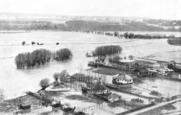
 The boatslides were built at the Thames locks to enable small boats to be pulled over sets of rollers round the locks, thus avoiding the waste of water caused by the locks constantly being opened for small craft. The peak of the traffic of small craft is at Boulter’s Lock, near Maidenhead. In 1911 a boat conveyer was built at this lock to relieve the congestion. It consists of a pair of bands, formed of transverse wood slats, carried on chain belts and driven by two 7½ horse-
