

© Wonders of World Engineering 2014-


Although the suspension and tubular bridges over the Menai Straits were built many years ago, they are
still classed among great engineering achievements. These remarkable bridges taxed all the
skill and ingenuity of their designers, Thomas Telford and Robert Stephenson
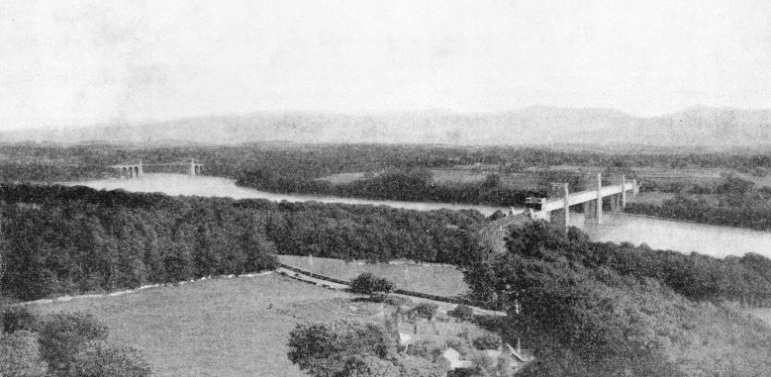
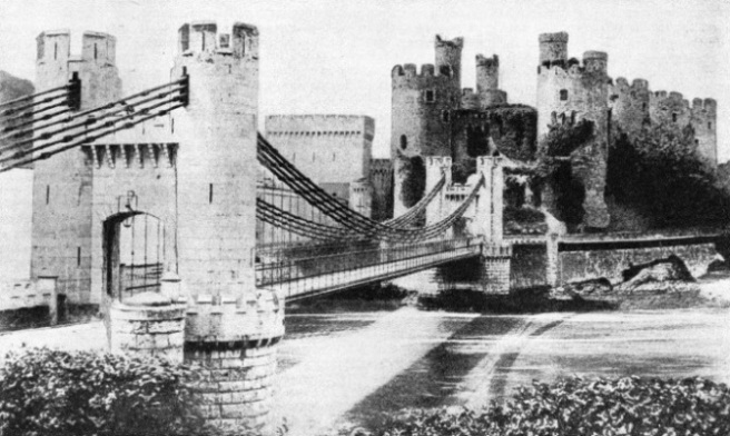
ACROSS THE MENAI STRAITS, which separate Anglesey (in the foreground) from the mainland of Wales, the main London-Holyhead road and the LMS main line from Chester to Holyhead are carried by two remarkable bridges. The fine suspension bridge (left) was built by Thomas Telford. For the railway bridges, its designer, Robert Stephenson, adopted an entirely new form of tubular structure. His bridge, the first of its kind, is known as the Britannia Tubular Bridge. Robert Stephenson built another and shorter tubular bridge on the same man line, at Conway, North Wales.
ACROSS the Menai Straits, which separate the island of Anglesey from the mainland of Wales, are two magnificent examples of the bridge-builder's art - the wonderful suspension and tubular bridges built by Thomas Telford and Robert Stephenson respec-
tively. The suspension bridge carries a road and the tubular bridge a railway. The Menai Suspension Bridge was built more than one hundred years ago and is still in use to-day, as is also the tubular structure, which was built a decade or so later.
In the eighteenth century Holyhead began to attract attention as the nearest port in North Wales to the Irish coast, and a packet service between that port and Ireland was inaugurated. At that time Holyhead was not easily reached from other parts of the country. The Welsh roads were atrocious and the crossing of the Menai Straits was, in certain states of tide and weather, most unpleasant. When the straits had been crossed, there remained the roads of Anglesey, which were, if possible, worse than those of the mainland. In 1810 the great engineer Thomas Telford was engaged to deal with the roads between Shrewsbury and Holyhead by way of Llangollen, Bettws-y-Coed and Bangor. He blasted rocks, built parapets and formed embankments until, in place of rough steep mountain tracks and tenacious quagmires, there was a wide, safe and splendidly graded road, which even at
this day is one of the best in Great Britain. But there still existed the irksome passage of the straits. Until these were bridged the road would be incomplete.
Telford found five ferries operating the straits, but the navigation was often dangerous. One ferry, working near the site of the present bridge, had an unenviable record during the previous half century.
Telford decided to span the straits with a bridge. He submitted to the Admiralty two plans for arched structures, one of which showed a 500 feet cast-iron arch, to be supported during construction on centres suspended from large frames rising on the two shores.
These plans were ruled out, however, on the ground that, they would interfere seriously with the navigation of the straits. Apart from satisfying the Admiralty there were the local pilots, who hotly contested the scheme, declaring that a bridge would make the
navigation of the waterway much more difficult and dangerous.
In the end Telford decided on a suspension bridge which should clear the water by 100 feet or more - sufficient to permit the passage of a tall ship. The site chosen was a point where the shore on either side rises steeply and where the straits are about 800 feet wide at high tide. The distance between abutments is just short of one third of a mile. To span this, Telford specified two short embankments, seven arches of 52½ feet span and a main suspension span over the channel of 550 feet between the centres of the towers.
The last factor taxed Telford's ingenuity severely. Such a span was at the time unprecedented. It called for a vast amount of preliminary experimental work, particularly in the matter of the huge chains which were to support the roadway.
An Act empowering the building of the bridge was passed in 1819 and Telford lost no time in getting to work. The foundations of the two main piers, each 153 feet high, were taken in hand first. While the piers rose, the arches of the two approaches rose with them, the chief difficulty being that of providing sufficient stone to keep the army of masons engaged. The stone was brought to the site from distant quarries in specially chartered vessels. On more than one occasion, just as a new load was about due, news would come that the ship had been wrecked on some lonely point on the Welsh coast, and the work would be delayed.
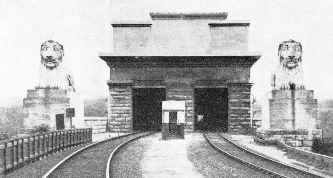
THE IMPOSING ENTRANCE to the Britannia Tubular Bridge. Over the portal are inscribed the words, “ Erected Anno Domini MDCCCL. Robert Stephenson, Engineer.” The rails are carried in eight tubes, two over each of the spans of the bridge. The tubes carry the track a distance of 1,511 feet and weigh about 5,000 tons. Stephenson designed the bridge to carry eight times the maximum train load that could be put upon it, and although the weight of rolling stock has greatly increased, the bridge is still more than strong enough for its work.
As the piers would be subjected to severe lateral strains, their individual stones were bound together by iron clamps, much in the same way as the components of a lighthouse. Telford left nothing to chance. A special machine was built to test the ironwork
used. Each bar had to pass a test twice as severe as that to which it would be subjected in the bridge. To facilitate the work of repair the method of building was such that any portion could later be taken out and replaced independently.
It was most important that the iron of the bridge should fit perfectly on to the stone. Although the masonry had been dressed as smooth as mason's tools could make it, yet neither its surface nor that of the iron castings was so smooth as to produce a perfect contact. The engineers, therefore, had recourse to the curious expedient of saturating two or three thicknesses of coarse flannel with white lead and oil, whereby a perfect fit was secured. Again, when the second set of the giant chains that were to carry the bridge had been put up, it was found that some of the links had been damaged, and the ingenious method was adopted of taking the strain off the damaged links one after another and replacing them without having in any way to disturb the position of the chain.
570-Feet Rectangular Chain
The chains are carried over the piers on large cast-iron saddles running on rollers. The easy movements of the chains over the rollers provide for the expansion or contraction as the temperature of the air varies. Since the efficiency of a chain depends ultimately on secure attachments, every care was taken to ensure a firm anchorage. The method adopted was to drive four parallel tunnels obliquely down into the native rock for a distance of 60 feet or more and to excavate a chamber across their lower ends. In this chamber were built up massive transverse anchorage frames, resting against the walls of rock separating the tunnels and therefore immovable unless the rock itself were tom away - a contingency that was virtually unimaginable.
The chains, sixteen in number, were composed of ½-in bars of iron. Thirty-six bars, corresponding to the strands of a wire cable, were grouped together to make a square chain 3-in on the side, the components of the chain being wrapped with iron wire. The weight of the portion of the chain between the two suspension piers was over 23 tons and its length was 570 feet.
The masonry completed, preparations were made for hoisting the chains into position - a process to which Telford looked forward with the greatest anxiety. To obtain exact figures as to the power required to hoist a chain and give it the correct curvature between the piers, he fastened together, end to end, a number of iron bars totalling 570 feet in length. These were laid out in an adjacent valley and raised at the ends until the centre was clear of the ground and the curve was the same as that of the intended suspension chains. From the stresses recorded, Telford calculated that a pull of 39½ tons would be needed to handle the central span of a chain.
Each chain was divided into three parts, two to reach from the anchorages to the piers, the third to span the channel. One of the land sections - that on the Carnarvon side - was long enough to extend down the seaward side of this pier to water level. The other reached only to the pier saddle. The rest of the chain was built on a raft 450 feet long and 6 feet wide, ready to be floated to a position between the two piers. On April 14, 1825, the hoisting of the first of the chains took place before the eyes of thousands of people who had gathered from far and near to witness the subjugation of the straits. In the afternoon, shortly before high water, the raft bearing the chain was taken in tow by four boats, swung round and moored across the straits on the line of the bridge. One end was then made fast to a loose end of the Carnarvon section, and to the other end were attached strong ropes leading over the top of the Anglesey pier to two capstans on the shore.
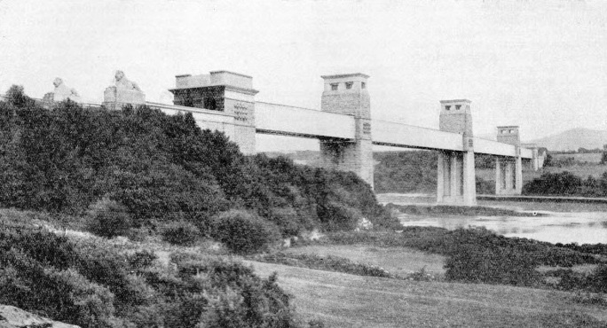
TOWERS AND ABUTMENTS of the Britannia Tubular Bridge were built while the iron tubes were being assembled on the shore. The central tower, known as the Britannia Tower because it rises from the Britannia Rock, is 230 feet high. For this tower 150,000 cubic feet of Anglesey marble and an equal quantity of limestone were used. The land towers reach to a height of 160 feet.
At the given signal 150 labourers threw their weight on the capstan bars. Slowly the chain rose from the raft, and yet more slowly as less and less weight was borne by the water. Presently a shout rose when the raft, now entirely freed from its load, floated down the tide. For another hour the crowd watched the curve of the chain grow flatter and flatter, and the word went round that a junction had been made with the Anglesey land section. A continuous chain now extended from Anglesey to the mainland.
This provoked a fresh outburst of cheering, which in turn encouraged some foolhardy workmen to use the chain as an unlicensed bridge and win the perilous honour of being the first to cross the straits by an aerial pathway. These men were not, however, as daring as a workman on the great cantilever bridge across the Niagara Gorge who, when but a narrow gap separated the two cantilever arms, laid a plank across it, walked deliberately to the middle and stood on his head, kicking his legs about just to show how little he cared for the whirlpool raging below.
The remaining fifteen chains were raised in the same manner as the first, and by July 9, 1825, the last was in place. A band ascended to a temporary platform on the centre of the span and played the national anthem to the crowds which had assembled for the occasion. Then followed the more prosaic work of attaching the roadway of stout planks to the vertical suspension bars of iron. By the end of the year the structure was complete and on January 30, 1826, a stage coach made the passage of the bridge at the head of a great procession of people of all ranks.
2,187 Tons of Iron
The bridge has a roadway length of just over 1,000 feet, and the suspension chains measure 1,715 feet from anchorage to anchorage. The roadway is 30 feet wide and there is also a footpath for pedestrians. More than 33,000 pieces of iron, weighing 2,187 tons, are incorporated in the structure, the cost of which was £120,000. During a gale the bridge oscillates slightly, but the crossing of heavy motor vehicles does not noticeably affect it.
Simultaneously with this bridge Telford built one of similar construction across the mouth of the Conway River, Carnarvonshire, to benefit travellers on the Chester-Holyhead road by abolishing the need for ferrying across the river. The Conway Bridge, which has a central span of 327 feet and a width of 32 feet, was also opened for traffic in 1826.
One of the main features of the Conway Bridge is the unusual design of the massive stone piers. The north end of the bridge is adjacent to Conway Castle, a Welsh stronghold dating from the thirteenth century. The masonry of the bridge is castellated to harmonize with the ancient style of architecture, and the roadway runs through stone portals.
Some forty years later came the building of the Menai Straits’ second crossing, the Britannia Tubular Bridge. Robert Stephenson, who had undertaken the building of a railway to Holyhead, decided that special bridges should be built to carry the trains over the River Conway and over the Menai Straits. The site he selected for the crossing of the straits was about a mile south of Telford’s suspension bridge, where the waterway is some 900 feet across at high tide. Here a rock, named the Britannia Rock, rising in mid-channel, offered a convenient base for a central pier.
As Telford had done, Stephenson first designed an arched bridge, having two spans of 450 feet each. Stephenson, too, incurred the displeasure of the Admiralty, which demanded a bridge that should give a clear headway of 100 feet right across the channel, not at certain points only. Furthermore, My Lords forbade the obstruction of the waterway while the bridge, of whatever type it should be, was being built.
The arch principle having been ruled out and the suspension principle being unsuitable, Stephenson’s choice was narrowed down to a stiff truss of some kind. Eventually he decided upon the tubular principle - huge iron tubes large enough for trains to run through them.
It was the mishap to the steamer Prince of Wales that gave him the idea. When this vessel was launched at Blackwall, on the Thames, she accidentally came in contact with the wharf, got jammed and remained suspended between the water and the wharf for a length of about 110 feet, but without any injury to the plates of the ship. This satisfactorily proved to Stephenson the great strength of wrought iron. He saw no reason why a wrought iron tubular structure could not be made of sufficient stiffness and strength to carry trains over gaps of 450 feet.
The question he had to decide was the form of the tube and the disposition of its metals. The design of the tube was not decided until after lengthy experiments, a sum of £6,000 having been spent on this work. Model tubes of one-sixth full size were built and tested, and from the results so obtained was established the superiority of rectangular tubes, specially strengthened at the top, over tubes of circular or elliptical design.
The following was the general plan of the bridge. On the Britannia Rock, and on the shores of the straits, at about high-water mark, would be built three huge piers of masonry, having openings 100 feet above high tide level for the tubes. The four tubes of the two main spans were to be 460 feet long, 15 feet wide and 30 feet high at the Britannia Tower, whence they slightly tapered vertically towards the shore. For the two land spans, four tubes, 230 feet long each, would be needed. All eight tubes were to be built up of riveted boiler plates, ranging from ½ in to ⅞ in thick, supported internally by strong ribs of angle iron and strengthened at the corners by triangular gussets to prevent distortion.
The roof of a tube was to be composed of eight flues, 21 in deep and 20 in wide, as various experiments had shown that a group of flues gave, for a fixed weight of metal, greater strength to the top member than could be obtained from plates assembled in the same way as those of the sides.
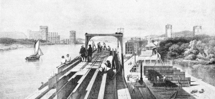
Stephenson decided to build the short land tubes in their final positions on “falsework” of stout timbers, and, as the Admiralty conditions prohibited this system for the main spans, to take a leaf out of Telford’s book and build the tubes for the main spans on platforms on the Carnarvon shore, float them between the piers, and raise them to their final elevation by hydraulic presses.
Building the Towers
Plans having been approved, preparations were begun for pushing the work ahead as vigorously as possible. Fifteen hundred workmen were collected and housed on the shores of the straits in wooden houses. Wharves, workshops and other temporary structures quickly rose. Ship after ship came to anchor in the straits, bringing iron plates from Liverpool, Anglesey marble from Penmon and red sandstone from Runcorn, in Cheshire, as wind and tide, shipping and convenience might determine. There was an unremitting clank of hammers, grinding of machinery and blasting of rock going on from morning till night.
The first task was the building of the towers and abutments, a great work in itself. The 230-feet high Britannia Tower alone consumed 150,000 cubic feet of Anglesey marble and as much limestone. Even greater quantities were needed for the two land towers, each 160 feet high. To make the elevation of the large tubes possible, vertical openings were left in the masonry of all three towers, in which the ends of the tubes would move upwards to their berths in the manner of the frame of a window in its sash.
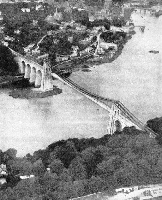
THE SUSPENSION BRIDGE across the Menai Straits from Bangor to Beaumaris has a central span of 550 feet, which in Telford’s day was unprecedented. The approaches to the central span carry the road over two short embankments and seven arches, each with a span of 52 ft. 6 in. Four of these arches are on the Anglesey side and three on the mainland side of the bridge. The roadway is suspended by iron rods from great chains which, anchored in the rock at either end, pass over the tops of the massive masonry piers.
While the towers and land spans were in progress, gangs of riveters working on the shore platforms joined up the plates and other members of the main spans. No fewer than 2,000,000 rivets, each 4 in long and ⅞ in diameter, and totalling 900 tons in weight, were used to hold the tube plates together.
When the first of the tubes approached completion, a portion of the wooden platform under either of its ends was removed and the rock beneath excavated to form a dock large enough to accommodate four pontoons, each 98 feet long, 25 feet wide and 11 feet in depth.
All eight pontoons were furnished with large valves through which the water passed in and out as the tides rose or ebbed. The combined buoyancy of the pontoons, 3,200 tons, exceeded the weight of the tube and its apparatus by about 1,400 tons.
By the middle of June 1849 tube No. 1 was ready for moving. In the upper part of each of the towers for which it was destined had been placed iron beams, 40 feet above the rectangular tube openings, to support a hydraulic press of 2,620 tons lifting power. Each of the two cylinders of a press was 9⅓ feet long, nearly 5 feet in diameter and 16 tons in weight. Its piston moved in a vertical direction.
