The remarkable increase in the use of engines driven by heavy oil fuel, ignited by the heat generated by compression of air, has had an effect on engineering practice comparable with that of the introduction of the steam engine
DOUBLE-ACTING MARINE DIESEL of the two-stroke cycle type built for the Italian liner Vulcania, a twin-screw vessel of 23,970 tons gross. The Vulcania is driven by two ten-cylinder engines of this type. They have a combined output of about 26,000 shaft horse-power at 128 revolutions a minute. At the farther end of the diesel in the photograph is the unit which supplies the scavenge air to the main unit.
THREE great sources of power are in use at the present day. There is water, the oldest, now coming into its own again in the great hydroelectric schemes; then steam, to which we owe the foundation of the modern mechanical world. Lastly there is the internal combustion engine, of which the best-known example is the petrol engine, first cousin to the older gas engine. It is the petrol engine that has enabled us to mechanize road transport to such an extraordinary extent. To the third division belongs the heavy oil engine, best exemplified in what is commonly known as the diesel.
Briefly, a diesel engine is an internal combustion motor which differs from the gas engine or from the petrol engine in that no sparking agency is required to effect internal combustion in the cylinders. It runs on heavy oil instead of on a highly volatile fluid or gas, and derives its ignition from the well-known natural law of heat generated by compression. Great compression invariably causes a rise of temperature, witness the existence of hot springs and other volcanic phenomena which are probably due to the exertion of great natural compressive forces in the crust of the earth. A familiar example of heat caused by compression occurs with the common bicycle pump. A spell of energetic pumping makes the long cylinder of the pump become decidedly warm. Some of that warmth may be ascribed to the internal friction of the piston, but most of it is caused by the rapid compression of air at each downward stroke of the piston.
In this age of motoring the principles of the ordinary explosion motor, or internal combustion engine, are known to most people. The idea dates back to the seventeenth century at least, when a Dutch student of physics, Christiaan Huygens, conceived the notion of moving a piston along inside a cylinder by exploding a charge of gunpowder.
Huygens, as might be expected, got no farther than the idea, though in it lay the germ of the gas engine and of the petrol motor. It was impossible to arrange for regular successive powder explosions in the cylinder of a workable engine. The petrol motor was made practicable by the invention of the electric sparking plug, by which the explosive mixture in the cylinder is ignited instantaneously at regular intervals, each time the piston finishes its upstroke. It is on this principle that the ordinary motor car engine of to-day works.
It is not to Diesel himself that we must look to trace the earlier stages in the evolution of what is known to-day as the diesel engine, but to Herbert Akroyd-Stuart. This notable mechanical engineer was born in 1864, and was trained as a practical engineer in his father’s works at Fenny Stratford, Bucks. During the middle ’eighties of the last century, when he was still little more than a boy, young Akroyd-Stuart began to exercise his constructive thought on problems associated with the early oil engines, and to devise means for obtaining a more easily running internal combustion motor.
He took out various patents between 1885 and 1890, and by then had produced something not dissimilar from the modern engine, though it remained for Diesel to introduce certain of its essential features. Scientists and engineers of high degree have hotly contested the relative claims of Akroyd-Stuart and Diesel to have been the originator of the modern heavy oil engine.
EARLY DIESEL ENGINE exhibited in the Science Museum, South Kensington. Dr. Rudolf Diesel was born in Paris on March 18, 1858. He developed the principle of Akroyd-Stuart’s oil engine by using high compression in the cylinders to provide the heat to ignite the mixture of fuel and air.
One of the causes of this difference of opinion is that the name of the German inventor has been perpetuated by the application of the term “diesel” to an entirely different development. This development was the airless injection of the fuel, that is, forcing it into the cylinder in an extremely fine spray under high pressure. The true diesel engine makes use of a jet of high-pressure air to carry the oil, and this involves an air compressor, an auxiliary on which, it is said, Dr. Diesel spent more time and trouble than on any other part of the engine. If a compression-ignition engine, so called to distinguish it from the spark-ignition engine, has airless injection it is not, strictly, a diesel engine. This distinction should be borne in mind. The airless injection engine was the invention of Akroyd-Stuart.
Akroyd-Stuart conducted his experiments on the following principle: that there are certain fuel mixtures, such as that involving the use of heavy oil, which are not readily volatile in the ordinary way, that is to say, they could not be exploded, in a confined space, by the occurrence of a spark. To all his engines he fitted what was called an ignition chamber - frequently known as a “hot bulb” - on the top of each cylinder head and communicating with the variable space between the cylinder head and the top of the piston. In this ignition space the air was heated by the compression caused on the return stroke of the piston.
The young inventor aimed at avoiding the premature ignition of the fuel mixture which would be caused by the use of a continuous spark. To avoid this he arranged for the fuel to be introduced through the valves into the cylinder after the returning piston had compressed the air in the cylinder head to the requisite degree. Then only did the fuel enter the hot compressed air of the ignition chamber of the engine and form an explosive mixture. Dr. Rudolf Diesel, to whom the modern heavy oil engine owes its name, was a French-born German, having been born on March 18, 1858, in Paris. As with many great pioneers, he did not live to see the greatest fulfilment of his invention, which has taken place during the past decade or so, for he lost his life in 1913 through falling overboard from a cross-channel steamer between Antwerp and Harwich.
Diesel’s principle, which first saw the light in 1892, was more advanced than that of Akroyd-Stuart. Akroyd-Stuart allowed a fairly low degree of compression in his cylinder and hot bulb, but Diesel made use of a high degree of compression and relied on that alone to explode the mixture in the cylinder. He described his patent as a system “developing motive work by means of heated air compressed to so high a degree that by the expansion subsequent to the combustion, the air is cooled about to atmospheric temperature, and that into this quantity of air, after its compression, fuel is gradually introduced. At this compression the temperatures become so high that the fuel employed is spontaneously ignited when it comes into contact with the compressed air”.
THE FOUR-STROKE CYCLE of diesel engines is illustrated diagrammatically. The induction valve, through which air is drawn on the downstroke of the piston, is marked C. The third stroke effects compression. At the critical moment fuel is injected through the nozzle A and the heat of the compressed air causes combustion. The exhaust valve D opens for the fourth stroke. B and E mark the air intake and exhaust pipes respectively.
Taking existing internal combustion practice, Diesel affirmed that it was impossible to increase the thermal efficiency of an engine when an explosive mixture was present in the cylinder before ignition took place. The injection of the fuel had to take place at the moment when compression was at its highest. This timing of the injection of the fuel at the critical moment of maximum compression goes to the credit of Akroyd-Stuart, who, in 1890, originated the practice of rapidly injecting a spray of oil by means of a pressure pump through nozzles into the hot compressed air as the piston approached the end of its stroke. This caused rapid combustion of the mixture inside the cylinder at an almost constant volume, the essential peculiarity of the modern oil engine.
The cycle, or complete action of one of the original diesel heavy oil engines took place in the following manner. First there was a down stroke of the piston, drawing unmixed air into the cylinder at atmospheric pressure, through an inlet valve at the top. Then came an upstroke, when the inlet valve automatically closed and the piston brought the imprisoned air to a pressure of from 500 lb to 600 lb per square inch.
Temperature of 1,000° F.
At the end of this stroke, and for a short period after, the fuel was admitted in a fine spray through the top. Combustion immediately ensued at an approximately constant volume and the piston was driven down on the third stroke by the expansion of the ignited mixture of air and fuel particles. The next stroke, the fourth in all, expelled the burnt residue of the mixture through an exhaust valve placed, in the same way as the admission valve, in the cylinder head.
This cycle of four strokes, two down and two up, gives to the motor its name of four-stroke engine. The rapid rate of compression occurring on the third stroke brought the temperature of the imprisoned air up to 1,000 degrees Fahrenheit, which was sufficient to cause ignition immediately the fuel was sprayed into it. It was necessary for the fuel to be injected at a pressure much higher than that of the air at the end of the upward compression stroke; otherwise it would make no headway against and into the hot compressed air.
The injection pressure in modern airless injection diesel engines may be anything up to 7,000 lb per square inch. This injection of the fuel is carried out by a special force pump driven by the engine, the fuel feed being regulated so as to project the fuel in a spray of tiny globules just before the piston has completed its upstroke, and continuing for a brief instant during the expansion, due to the evolution of gas from the fuel, which sends the piston down again. The atomization of the fuel is essential to obtain a thorough mixture with the fuel air. After the cutting off of the fuel spray on the downstroke, the ignited mixture expands at diminishing pressure, giving an impulse to the descending piston, and producing an effect not dissimilar to that of steam expanding in the cylinder of a steam engine.
This action is different from the more rapid impulse of the spark-fired pseudo-explosion in the cylinder of a petrol engine, and scientifically much superior. The valves for the admission and expulsion of the combustion air are of the mushroom-shaped “poppet” type, such as Lentz and other engineers have, during recent times, applied to the cylinders of steam engines in place of the older slide-valves and piston-valves.
Poppet valves are worked automatically by the motion of the engine, through a camshaft-operated valve gear. There is another important difference here between the diesel engine and the steam engine. In the steam engine the steam itself keeps the cylinder at a constant temperature and no external cooling devices are needed. The compression and combustion in the cylinder of the diesel engine, on the other hand, producing high temperatures as they do, necessitate an efficient cooling system for the cylinder in the form of a water jacket, with means for keeping the cooling water in circulation. Exactly the same process is observed in a large petrol engine, such as is found on almost every road motor vehicle of any size.
MOBILE POWER HOUSE at the head of a train on the Buenos Ayres Great Southern Railway, in Argentina. A diesel-generator set of 1,700 brake horse-power is mounted on this vehicle. Current is fed to traction motors fitted to every coach in the train.
Another difference between the working of diesel and petrol engines and that of steam engines is that the internal combustion motor is often single-acting, that is to say, the motive force is brought to bear on one side of the piston only. The standard steam engine, however, is generally double-acting, steam being admitted at either end of the cylinder and pressing alternately on the two surfaces of the piston.
In recent years, mechanical engineers have adopted the two-stroke engine to an increasing extent in diesel practice. In the four-stroke engine, every other downward movement of the piston is a power stroke; in the two-stroke engine the piston is exposed to explosion of the fuel mixture on every downstroke. Fewer cylinders are therefore necessary in a two-stroke engine equal in power to a given four-stroke engine. This gives a corresponding economy in weight compared to the power output.
In the cylinder of a two-stroke engine the inlet and exhaust ports, instead of opening through the poppet valves in the top, enter at intermediate positions in the sides. They are opposite to one another, without valves, and with the inlet slightly below the level of the exhaust port. The normal position of the fuel spray, as before, is in the top of the cylinder above the head of the piston.
As the piston nears the bottom of the stroke, the exhaust gases are discharged through the exhaust port, then the fresh air for the next explosion passes through the inlet. The piston, having completed its downstroke, comes up again, covering the ports, imprisoning the air and compressing it into the top of the cylinder. At the critical moment of compression, the feed nozzle in the cylinder top injects its spray of fuel, forming a mixture, which automatically burns rapidly through the heat of compression, driving the piston down to the bottom of the cylinder again. Thus a complete cycle is performed with the two strokes, one up and one down. As the piston passes below the level of the exhaust and inlet ports the process is repeated.
In the diesel engine, as in certain petrol and steam engines, the flow of the fuel can be automatically regulated by a valve controlled by a centrifugal governor, on the principle devised by James Watt for application to his early steam engines more than a century and a half ago.
Another feature needing careful attention is the system of injecting the fuel into the cylinders. There are many such systems in general use, but the principal features and requirements of injection are much the same. It is not merely necessary for the injection system to pass tiny and accurately-timed quantities of fuel into the cylinder during the peak of compression, but it
must also atomize it, that is to say, reduce it to small globules of constant size as it passes into the hot compressed air.
The injection nozzle may have one orifice, or it may be of a multiple-orifice type, corresponding to the rose of a syringe. The placing of the nozzle varies. It may lead through the head or the side of the cylinder. It may, on the other hand, discharge into a “turbulence” chamber on the top of the cylinder head, forming a clerestory or raised section in the head with the lower end open to the space between cylinder head and piston. The orifice between this clerestory chamber and the cylinder itself is circular, and the boss of the piston head fits into it at the top of the stroke.
The fuel has to pass through the injection nozzles at a high pressure and, just as a carburettor and float chamber regulate the flow of fuel to the cylinders of a petrol engine, so does some means of compression, worked automatically by the motion, feed the injection nozzles of a diesel and regulate their discharges into the cylinders. With airless injection, a system of cam-operated, spring-loaded valves passes the fuel into the cylinders at pressures ranging from 4,000 lb to 7,000 lb per square inch. Air injection is effected by a blast of air from a storage reservoir working in conjunction with a compressor, at a pressure of about 1,000 lb per square inch.
The diesel cannot start itself. A downstroke is necessary to fill the cylinder with air, ready for compression and the formation of the combustible mixture. Designers of diesel engines have, therefore, incorporated various forms of starter. Some of these have come into general use; others have so far been applied only experimentally. The diesel engine may receive its primary motive impulse from a small petrol engine, which turns the crankshaft of the main engine until compression in the cylinders of the main engine initiates combustion. More commonly, however, this service is performed by an electric motor or by a compressed-air motor. The electric motor begins to operate as soon as the current is turned on, and the compressed-air motor, the principle of which is identical with that of the steam engine, also needs no self-starting device of its own, the pistons reacting immediately to the first introduction of compressed air.
ENGINE COMPARTMENT OF DIESEL-ELECTRIC RAILCAR used by the Buenos Ayres Railway, Argentina. This type of propulsion is becoming increasingly popular for railways. The diesel engine illustrated develops 270 brake horse-power at 1,100 revolutions a minute.
The ever-increasing use of diesels during recent years has been remarkable above all in the transport field. With the corresponding increase in the use of petrol engines, this is not to be wondered at; for of all internal combustion engines, few can show a greater working economy in relation to its power output than the modern diesel. On the other side is the disadvantage of price, for the first cost of the diesel engine is relatively high. Manufacturers of heavy road vehicles, however, have tended more and more to substitute the heavy oil engine for the petrol engine; some years have already elapsed since the builders of London’s buses began to install heavy oil engines in place of petrol motors in these vehicles. One firm which for many years has been famous for its steam road wagons has recently made a sudden change to diesel propulsion. The steam engine is a simple machine and ideal for certain classes of road transport. Recent taxation legislation, however, has hit the steam wagon badly, causing the cost of its upkeep suddenly to rise considerably above that of an internal combustion engine. The diesel engine was the best substitute for steam for these heavy road wagons, and above all enabled their owners to avoid paying the higher rate of taxation.
At first, the railways were rather chary of the diesel. Although the period since the end of the war of 1914-18 saw the great modern development of diesel engines, the future of traction on railways was in a state of flux. The steam locomotive was a well-tried and well-proved machine, ideal for certain classes of work. It had its limitations in other directions and had already been replaced by the electric motor in many places where a form of traction having better powers of acceleration was most desired. At that time, however, the pros and cons of electrification were still uncertain and hotly debated by experts. Certain classes of traffic existed which it would not pay to electrify, but for which the steam engine of long tradition was cumbersome and otherwise unsuitable. A tiny but complete example of this is the little North Sunderland Railway, between Chathill and Seahouses in Northumberland. The four miles of line are covered by one light train working a shuttle service. Here electrification was not worth while, and to use a steam engine was comparable to using a coal hammer to crack a cobnut. The traffic of the North Sunderland Railway to-day is worked entirely in normal conditions by one diesel locomotive.
“Lightning Trains”
At the present time, a considerable number of diesel locomotives are at work on the British main-line railways. Such locomotives have, however, been generally confined to shunting operations. Continental engineers have been most active in the application of the diesel to rail transport. Switzerland made a vigorous start in the early nineteen-twenties, but the great advantages of electrification, backed by Switzerland’s almost infinite water power resources, has stultified diesel rail traction in that country. It was at Winterthur, however, that the first diesel locomotive was built and there extensive experiment and research are being carried out.
A recent development, which has so far been most conspicuous in Germany, Denmark, Holland and the United States, has been the application of diesel propulsion to special light high-speed trains travelling over long distances, and carrying a strictly limited number of passengers who pay slightly increased fares. Examples of these are the well-known Flying Hamburger and its companion trains in Germany; the Zephyr of the Chicago, Burlington and Quincy Railway, and the great American transcontinental expresses of the Union Pacific. In Denmark trains of this kind supplement the ordinary expresses; preceding them at a much higher speed. They are called, in Danish, Lyntog, or “Lightning Trains”. The secret of their success lies in rapid acceleration and sustained high speed.
A GIANT PISTON from the ten-cylinder marine diesel engine illustrated at the top of this page. The cylinders of this engine have a bore of 750 millimetres (29·53 inches) and a stroke of 1,250 millimetres (49·21 inches or more than four feet).
Denmark has adapted the diesel today to every class of railway traction, and there is evidence of its success in the fact that recently the Danish State Railways announced that no more steam locomotives would be built for work on their lines. The same thing has happened in Holland, where, however, diesel and electric traction are being introduced side by side, electric traction on the more congested routes. Other countries, too, are making extensive use of the new form of traction.
For traction purposes direct drive has been tried, but without success. The disadvantages of this arrangement are dependent on the manner in which a diesel engine has to be started. It cannot be expected to exert any appreciable tractive force until its revolution speed is approaching the maximum. For this reason diesel engineers have adopted various transmission systems, of which the diesel-electric system is one of the commonest. This system is used for heavy work and the motive power is electricity. The diesel engine drives a dynamo, which in its turn supplies current to the traction motors, the vehicle thus becoming a travelling power station independent of current supply from an external source.
For smaller vehicles on rail or road - passenger or express goods railcars, lorries, buses - mechanical transmission has a wide field. In this, the designers have arranged a system of bevel wheels and sliding gear wheels operating through clutches, by which the engine is let into gear when its revolution speed reaches the required rate. Mechanical transmission has not been used, generally, for heavy work, the maximum power of a diesel engine operating through this means being about 400 horse-power. Experiments involving engines of higher power output have, however, been made, notable among them being the application by Professor Lomonossof of mechanical transmission to a large diesel locomotive on the Russian railways.
Motorship Practice
In hydraulic transmission, use is made of what is known as the fluid flywheel. This also is ideally applicable to light vehicles running on road or rail. The principle of the fluid flywheel is as follows: the driving shaft from the engine and the transmission shaft both enter a closed chamber filled with oil. The two shafts face each other, and each bears a vane wheel immersed in the oil. At first the vane wheel on the engine shaft, revolving in the oil, exerts little force on it, but as its speed rises the circular agitation of the oil causes the vane wheel of the transmission shaft to revolve in sympathy. Thus there is no jerking in starting, such as is experienced with certain gear systems, especially when they are carelessly operated.
German engineers in particular have made experiments with compressed-air transmission for heavy work. In this, as applied to a large railway locomotive, there are virtually two engines. First there is the diesel, running at high speed and operating a powerful air compressor. The air from this drives the locomotive along through a system of cylinders and motion to all intents and purposes identical with that of a steam locomotive. The appearance of the machine is that of a perfectly ordinary railway engine with no boiler, and with its upper part, above the running plates, covered with a long, all-over cab, similar to that of an electric locomotive, and equipped with a big radiator connected with the cooling installation.
In the Still engine the designer has produced a combined steam and diesel engine to overcome starting difficulties. The engine is equipped with a, relatively small boiler, and is started by steam drawn from the boiler. As speed increases, the diesel cylinders begin to function, when the engine is running by steam power and oil power. Finally, when the diesel has reached a speed approaching the maximum, the steam may be shut off and the engine run by oil power alone.
Recent years have seen a remarkable increase in the application of diesel power to the propulsion of ships. The total number of motorships entered in Lloyd’s Register Book for 1914-15 was 297, with a total gross tonnage of 234,287. After the war of 1914-18 motorship building proceeded apace. Lloyd’s Register figures for 1919-20 showed 912 motorships, with a total gross tonnage of 752,606. By 1929-30 the number of motorships had nearly quadrupled and the gross tonnage had increased nearly ninefold, the figures being 3,246 and 6,628,102 respectively. These totals were nearly doubled in the 1936-37 Register, with 6,128 motorships having a total gross tonnage of 12,290,599.
One of the largest motorships is the Augustus, of the Italia Line. Built in 1927, she has a gross tonnage of 30,418. Two British examples are the Georgic and the Britannic, of the Cunard White Star Line, with gross tonnages of 27,759 and 26,943 respectively. The Union Castle Line built two passenger motorships in 1936 for its England-South Africa service. These are the Athlone Castle, of 25,564, and the Stirling Castle, of 25,550 tons gross.
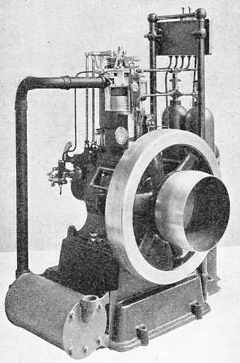
SIX-CYLINDER DIESEL ENGINE for heavy commercial motor vehicles. This is an oil engine which develops 115 horse-power. The cylinders have a bore of 105 millimetres and a stroke of 146 millimetres.


 He took out various patents between 1885 and 1890, and by then had produced something not dissimilar from the modern engine, though it remained for Diesel to introduce certain of its essential features. Scientists and engineers of high degree have hotly contested the relative claims of Akroyd-

 The diesel cannot start itself. A downstroke is necessary to fill the cylinder with air, ready for compression and the formation of the combustible mixture. Designers of diesel engines have, therefore, incorporated various forms of starter. Some of these have come into general use; others have so far been applied only experimentally. The diesel engine may receive its primary motive impulse from a small petrol engine, which turns the crankshaft of the main engine until compression in the cylinders of the main engine initiates combustion. More commonly, however, this service is performed by an electric motor or by a compressed-
 A recent development, which has so far been most conspicuous in Germany, Denmark, Holland and the United States, has been the application of diesel propulsion to special light high-